Cooling device of hybrid-type

a cooling device and hybrid technology, applied in the direction of air heaters, indirect heat exchangers, light and heating apparatus, etc., can solve the problems of reducing the life expectancy, deteriorating the performance of semiconductor devices, and increasing the heat emission ratio of semiconductor devices per unit area, so as to improve cooling performance and minimize heat loss

Inactive Publication Date: 2006-11-30
CELSIA TECH TAIWAN INC
View PDF1 Cites 62 Cited by
  • Summary
  • Abstract
  • Description
  • Claims
  • Application Information

AI Technical Summary

Benefits of technology

[0009] In addition, it is another object of the present invention to provide a compact type hybrid cooling device capable of improving cooling performance by minimizing the loss of heat transfer through fins, as the hybrid cooling device is disposed between the fins.
[0010] In addition, it is further another object of the present invention to provide a compact type hybrid cooling device capable of performing cooling regardless of the effect of gravity.

Problems solved by technology

As design rule decreases due to the trend towards large scale integration of semiconductor devices, and thereby the line width of electronic devices constituting semiconductor devices narrows, small-sized and high performance electronic equipment has been achieved owing to a larger number of transistors per unit area, which causes, however, that the ratio of heat emission of a semiconductor device per unit area increases.
The increase of the rate of heat emission deteriorates the performance of semiconductor devices and lessens the life expectancy thereof, and eventually decreases the reliability of a system adopting semiconductor devices.
Particularly in semiconductor devices, parameters are too easily affected by operation temperatures, and thereby that further deteriorates properties of integrated circuits.
The fin-fan type cooler which compulsorily cools devices using fins and / or fans has been used for tens of years, but has some defects such as noise, vibration, and low cooling efficiency compared to its large volume.
Although the peltier type cooler doesn't make noise or vibration, it has a problem that it requires too many heat dissipation devices at its hot junction needing large driving power in accordance with the law of conservation of energy.
The water-jet type cooler goes mainstream in cooling device research because of its efficiency, but its structure is complicated due to the use of a thin film pump driven by an external power supply, and it is significantly affected by gravity, as well as a problem that it is difficult to achieve robust design when applied to personal mobile electronic equipment.
In addition, there is a problem that its installation location is significantly restricted because the evaporated refrigerant is transferred depending on the difference between buoyancy and pressure in the heat pipe, and the liquefied refrigerant in the heat pipe depends on gravity due to the structure and size of the medium of the returning section.
Further, since the amount of heat produced by a highly integrated semiconductor device such as an up-to-date CPU is so large that the conventional cooling device cannot deal with the heat, even the cooling device 10 combining heat pipe and fin-fan can manage to cool only when equipped with three or four of the heat pipes 12 and two or more of the fans 16.
If the elements increase as above, the size of the device becomes too large, and besides noise and power consumption by lots of the fans 16 also increase considerably, so that it isn't useful any more.
The disadvantage of the convention heat pipe type cooler as above is that the loss of heat transfer at the fins themselves rapidly drops in comparison to the heat transfer at the phase transition medium, because it has to transfer heat through fins of large area even though utilizing phase transition of fluid.

Method used


Image

  • Cooling device of hybrid-type
  • Cooling device of hybrid-type
  • Cooling device of hybrid-type

Examples


first embodiment

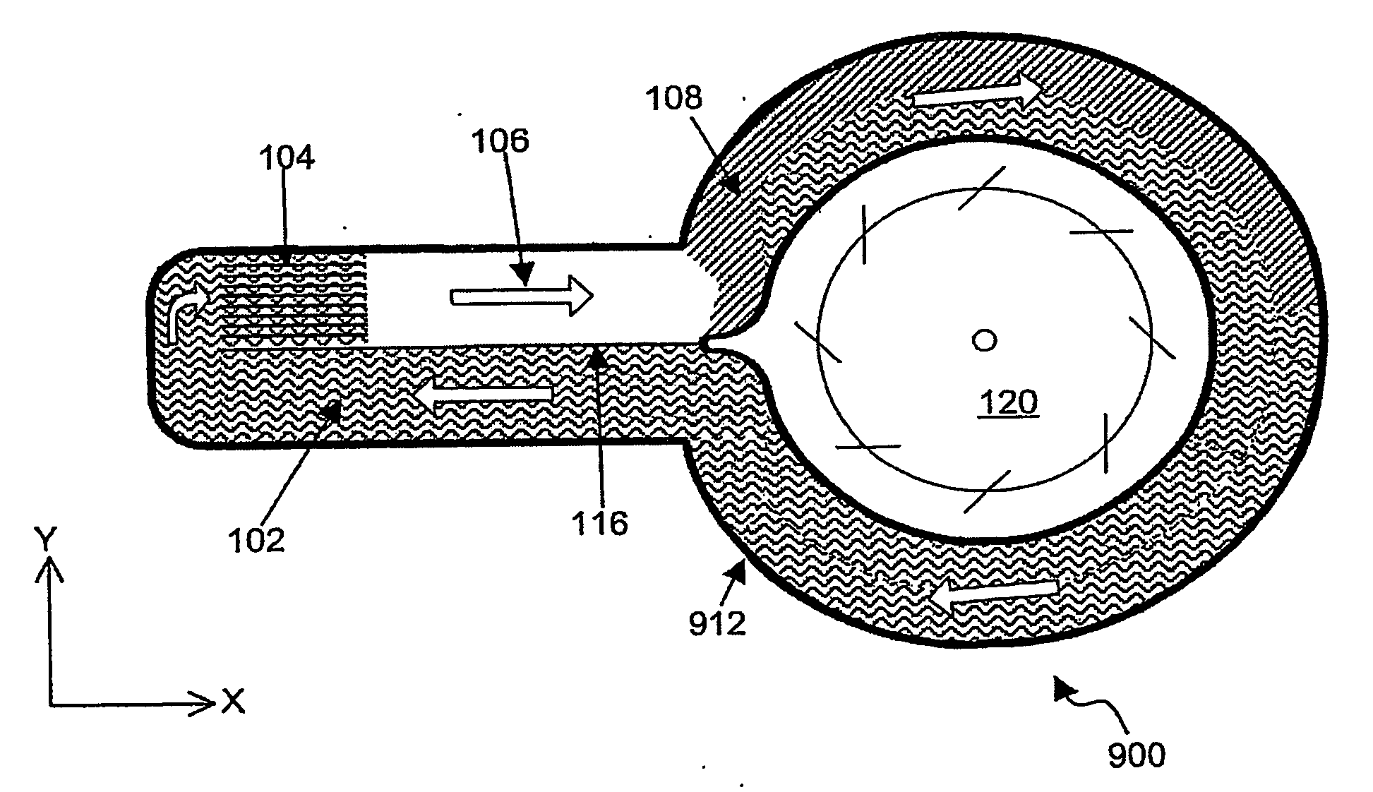
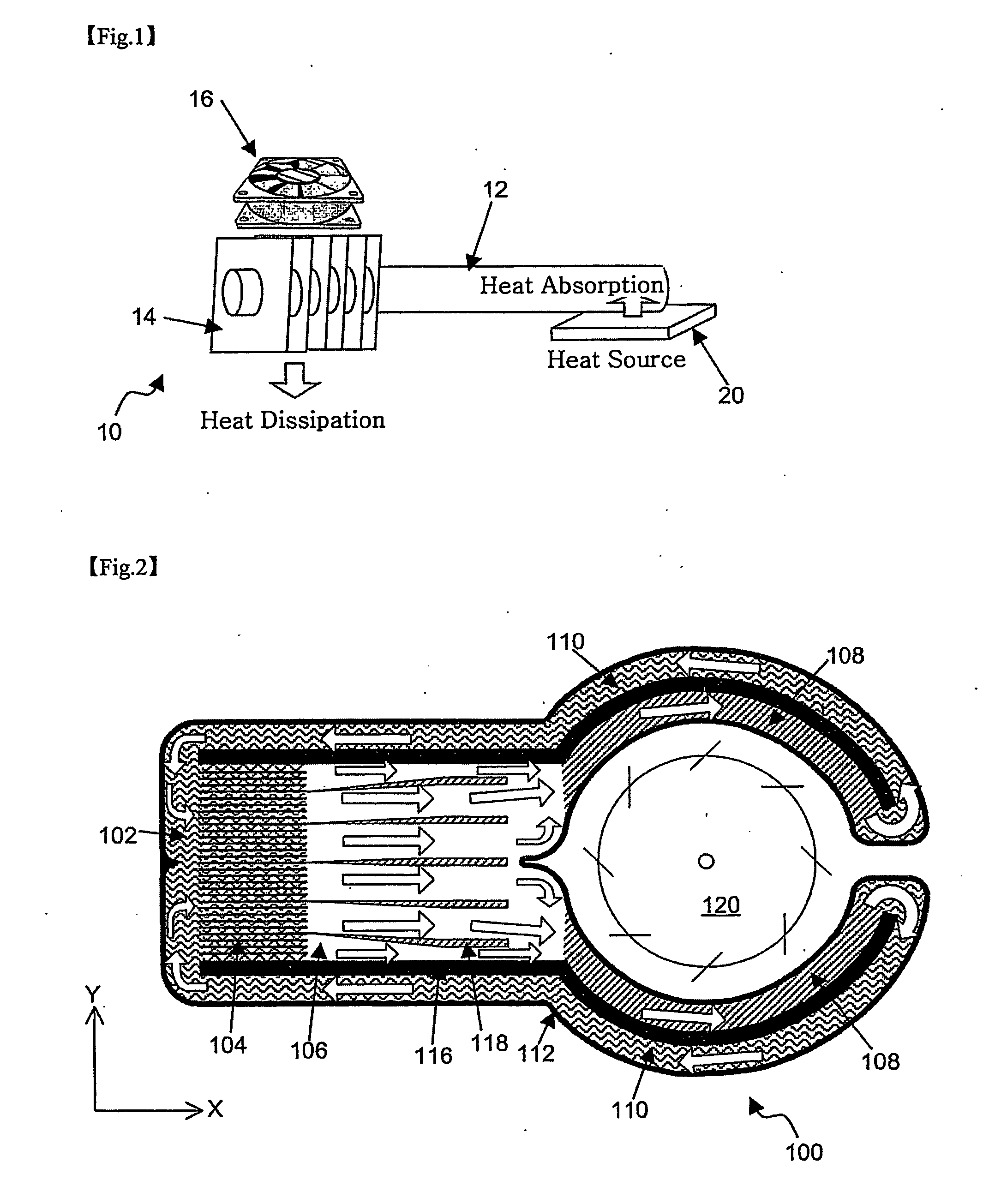
[0030]FIG. 2 shows a horizontally cross-sectional view of a hybrid cooling device according to the present invention. As shown in FIG. 2, the hybrid cooling device 100 of this embodiment includes a phase transition cooler 112 in which a circulation loop of a refrigerant capable of phase transition is formed, in at least a part of the circulation loop including a section (hereinafter, “branching section”) in the shape of a hollow ring, and a fan 120 being disposed in the hollow of the branching section of the phase transition cooler.

[0031] A housing of the phase transition cooler 112 can be manufactured of a material such as semiconductor, e.g. Si, Ga, etc., a novel substance-laminated material, e.g. Self Assembled Monolayer (SAM), metal and / or alloy, e.g. Cu, Al, etc. with high conductivity, ceramic, a high molecular substance, e.g. plastic, a crystalline material, e.g. diamond. Particularly, in case of a semiconductor chip as the external heat source, the housing can be made of the...

second embodiment

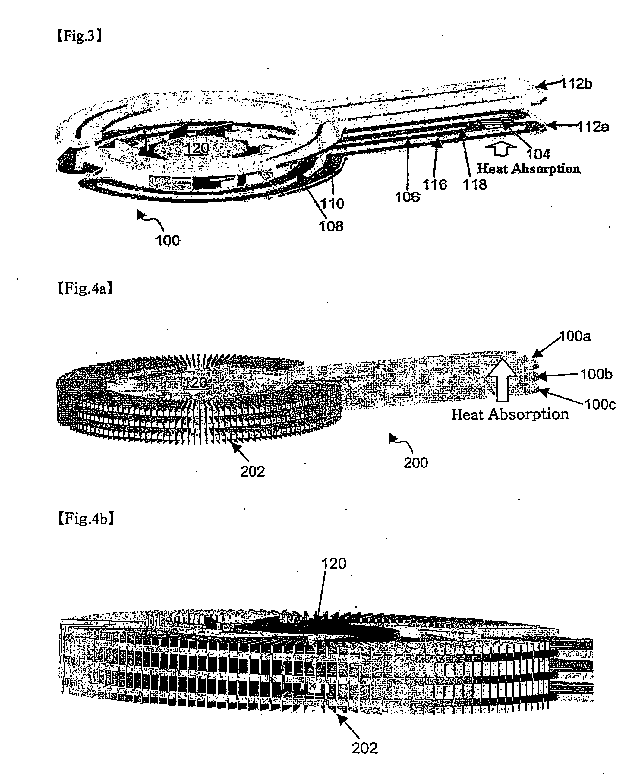
[0056]FIG. 4a shows a perspective view of a hybrid cooling device 200 according to the present invention, and FIG. 4b shows an enlarged perspective view of a condensation section of the hybrid cooling device 200. As shown in the drawings, a plurality of phase transition coolers 100a, 100b and 100c are arranged vertically in this embodiment. The heat from the external source is transferred to a region corresponding to the evaporation sections of the phase transition cooler 100a, 100b and 100c respectively in the thick arrow direction. For this, a heat transfer substance can be inserted between the phase transition coolers 100a, 100b and 100c.

[0057] In this embodiment, a plurality of fins 202 are radially formed outside the condensation sections of the phase transition coolers 100a, 100b and 100c, and a fan 120 is disposed in the middle space. Accordingly, unlike the conventional heat pipe module, the temperature distribution inside the fins is uniformly maintained, which maximizes t...

third embodiment

[0058] Next, FIG. 5a shows a perspective view of a hybrid cooling device 220 according to this invention, and FIG. 5b is a side view of the hybrid cooling device 220 in FIG. 5a. As shown in the drawings, the cooling device 220 in this embodiment is formed by bonding the sections including the refrigerant storage sections and the evaporation sections of the phase transition coolers 100a, 100b and 100c shown in FIG. 4a. The sections including the condensation sections are not bonded but separated so as to maximize the ventilation effect by the fan 120, and the side structure of the phase transition coolers of the lowest and middle layers are consequently modified a little.

[0059] Meanwhile, in this embodiment, the liquid state refrigerant transfer sections near the evaporation sections and the evaporation sections, each of which is included in the three layer phase transition coolers, may be formed in common rather than independently. In this case, a predetermined region branches verti...


PUM

PropertyMeasurementUnit
phase transitionaaaaaaaaaa
thermally insulatingaaaaaaaaaa
thermal insulationaaaaaaaaaa

Abstract

The present invention provides a hybrid-type cooling device which can perform cooling by phase transition, ventilation and convection.

Description

TECHNICAL FIELD [0001] The present invention relates to a cooling device for cooling a semiconductor integrated circuit device, etc., and more particularly to a hybrid (or composite) cooling device adopting both cooling systems based on phase transition of moving fluid and a fin and / or fan. BACKGROUND ART [0002] As design rule decreases due to the trend towards large scale integration of semiconductor devices, and thereby the line width of electronic devices constituting semiconductor devices narrows, small-sized and high performance electronic equipment has been achieved owing to a larger number of transistors per unit area, which causes, however, that the ratio of heat emission of a semiconductor device per unit area increases. The increase of the rate of heat emission deteriorates the performance of semiconductor devices and lessens the life expectancy thereof, and eventually decreases the reliability of a system adopting semiconductor devices. Particularly in semiconductor devic...

Claims


Application Information

Patent Timeline
Patent Type & Authority Applications(United States)
IPC IPC(8): F28D15/00F25B1/00F28D20/02F28D15/02F28D15/04H01L23/427
CPCF28D15/0233F28D15/0266F28D15/046F28F2210/02H01L23/427H01L2924/0002F28F2245/02H01L2924/00Y02E60/14F28D20/02
Inventor CHOI, JAE JOONPARK, JIHWANGLEE, JEONG HYUN
Owner CELSIA TECH TAIWAN INC
Why Eureka
Try Eureka