Active matrix display device, method for driving the same, and electronic device
a technology of active matrix and display device, which is applied in the direction of static indicating device, electroluminescent light source, instruments, etc., can solve the problems of variable luminance of each pixel, and achieve the effect of reducing the number of times signal writing to a pixel, reducing power consumption, and reducing power consumption
- Summary
- Abstract
- Description
- Claims
- Application Information
AI Technical Summary
Benefits of technology
Problems solved by technology
Method used
Image
Examples
embodiment mode 1
[0195] In this embodiment mode, detailed explanation is made on a display device and operation thereof in the case of applying the present invention to a time gray scale method.
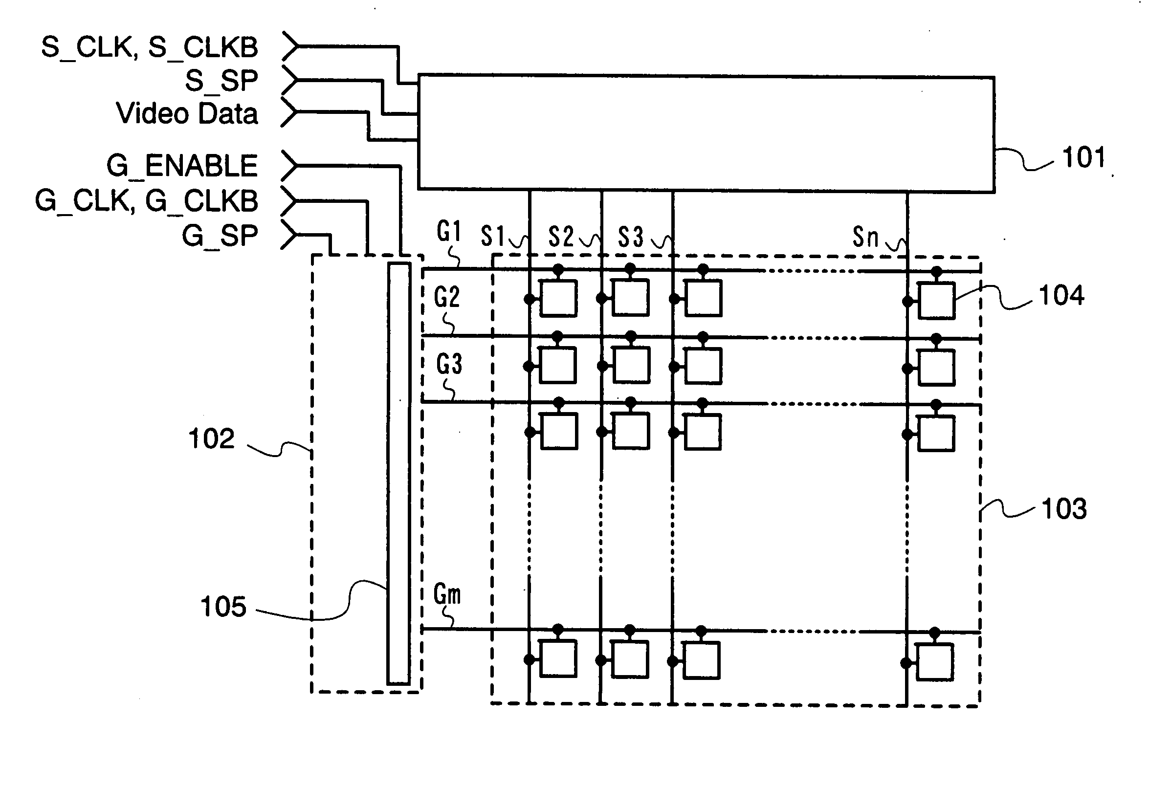
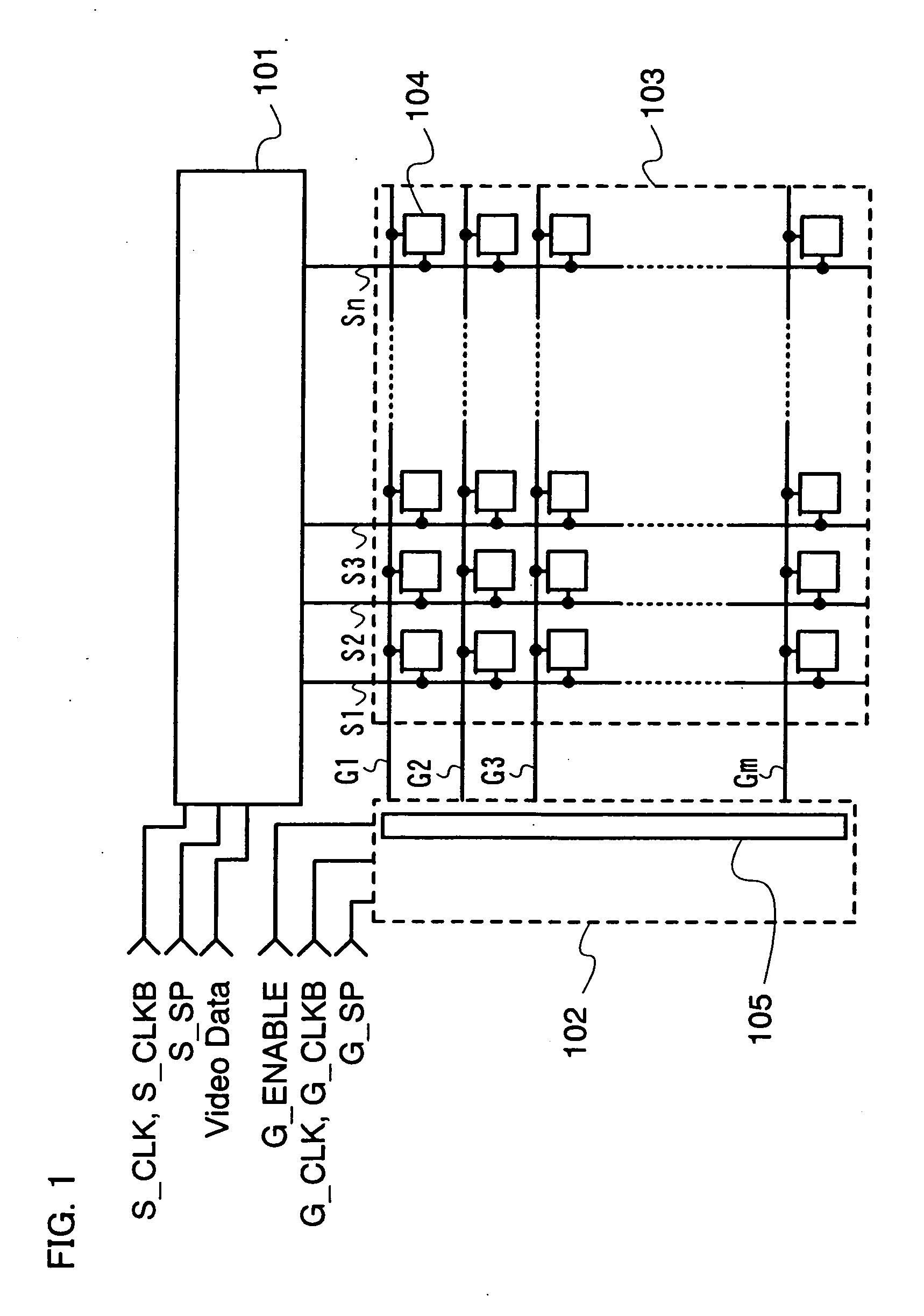
[0196] A display device shown in FIG. 1 includes a signal line driver circuit 101, a scan line driver circuit 102, and a pixel portion 103. In addition, a plurality of pixels 104 is arranged in matrix in the pixel portion 103 relative to signal lines S1 to Sn extended from the signal line driver circuit 101 in a column direction and scan lines G1 to Gm extended from the scan line driver circuit 102 in a row direction. In addition, the scan line driver circuit 102 includes an output control circuit 105.
[0197] Signals such as a clock signal (G_CLK), an inverted clock signal (G_CLKB), a start pulse signal (G_SP), and an output control signal (G_ENABLE) are input to the scan line driver circuit 102.
[0198] The clock signal (G_CLK) is a signal alternating between H (High) and L (Low) at regular intervals, and th...
embodiment mode 2
[0221] In this embodiment mode, explanation is made on a line sequential display device of the present invention and operation thereof.
[0222]FIG. 3 shows a schematic diagram of a line sequential display device. A signal line driver circuit 301 corresponds to the signal line driver circuit 101 of the display device in FIG. 1. Other common components are denoted by reference numerals in common with those in FIG. 1, and explanation thereof is omitted.
[0223] The signal line driver circuit 301 includes a pulse output circuit 302, a first latch circuit 303, a second latch circuit 304, and an output control circuit 305.
[0224] A clock signal (S_CLK), an inverted clock signal (S_CLKB), a start pulse signal (S_SP), and the like are input to the pulse output circuit 302. Then, a sampling pulse is output in accordance with the timing of these signals.
[0225] A sampling pulse output from the pulse output circuit 302 is input to the first latch circuit 303. A video signal (Video Data) is input...
embodiment mode 3
[0279] Subsequently, FIG. 4 shows a schematic diagram of a dot sequential display device. A signal line driver circuit 401 corresponds to the signal line driver circuit 101 of the display device in FIG. 1. Other common components are denoted by reference numerals in common with those in FIG. 1, and explanation thereof is omitted.
[0280] The signal line driver circuit 401 includes a pulse output circuit 402, a switch group 403, and an output control circuit 404.
[0281] A clock signal (S_CLK), an inverted clock signal (S_CLKB), a start pulse signal (S_SP), and the like are input to the pulse output circuit 402. Then, a sampling pulse is output in accordance with the timing of these signals.
[0282] A sampling pulse output from the pulse output circuit 402 is input to the switch group 403. A video signal (Video Data) is input to respective one of terminals of switches in the switch group 403, and the respective other terminal is connected to respective one of signal lines S1 to Sn throu...
PUM
 Abstract
Description
Claims
Application Information
 - R&D
- Intellectual Property
- Life Sciences
- Materials
- Tech Scout
- Unparalleled Data Quality
- Higher Quality Content
- 60% Fewer Hallucinations
Browse by: Latest US Patents, China's latest patents, Technical Efficacy Thesaurus, Application Domain, Technology Topic, Popular Technical Reports.
© 2025 PatSnap. All rights reserved.Legal|Privacy policy|Modern Slavery Act Transparency Statement|Sitemap|About US| Contact US: help@patsnap.com


