Image display unit

a display unit and image technology, applied in the field of hold type image display units, can solve the problems of slow response speed of hold type display units such as the liquid crystal display units, inability to solve blurriness, and after-image generation, etc., to reduce the burden on the operating speed of a circuit or a circuit scale, reduce the blur of moving images, and achieve the effect of reducing the burden of circuit or circuit scale operation speed

Active Publication Date: 2006-11-30
JVC KENWOOD CORP A CORP OF JAPAN
View PDF1 Cites 29 Cited by
  • Summary
  • Abstract
  • Description
  • Claims
  • Application Information

AI Technical Summary

Benefits of technology

[0009] In view of the above-described problems, it is an object of the present invention to provide an image display unit which can reduce a moving image blur without deteriorating advantages of hold type display which can perform display without flickering. Further, it is another object of the present invention to provide an image display unit which can be readily realized with a reduced burden on an operating speed of a circuit or a circuit scale when decreasing a moving image blur.
[0014] According to the present invention, a moving image blur can be reduced without deteriorating advantages of the hold type display which can perform display without flickering.
[0015] Further, according to the present invention, the interpolation video signal which is generated to increase a frame frequency and the base video signal are subjected to time base emphasis processing by utilizing a correlation between preceding and following video signals before actually increasing the frame frequency. Therefore, a circuit can be readily realized without a need of increasing an operating speed of the time base emphasizing circuit.
[0016] Further, since the number of frame memories can be reduced and a special circuit such as one which shuts a backlight is not required, an increase in cost can be suppressed.

Problems solved by technology

Since a response speed of the liquid crystal display unit is slow, the liquid crystal display unit has a problem that an after-image is generated when a moving image is displayed.
A hold type display unit such as the liquid crystal display unit, however, cannot solve blurriness (which will be referred to as a moving image blur) of a moving image caused by an influence of a visual system integration owing to hold display itself even if a response speed of the liquid crystal is increased.
The first method has a problem that means for shuts a backlight in synchronization with a video signal is required and display without flickering which is an advantage of the hold type display is deteriorated (a first problem).
The second method has a problem that a sampling frequency of a video signal and a writing speed of a liquid must be respectively doubled and this operation imposes a great burden on a circuit scale or an operating speed of a circuit, thus involving a practical difficulty (a second problem).

Method used


Image

  • Image display unit
  • Image display unit
  • Image display unit

Examples


first embodiment

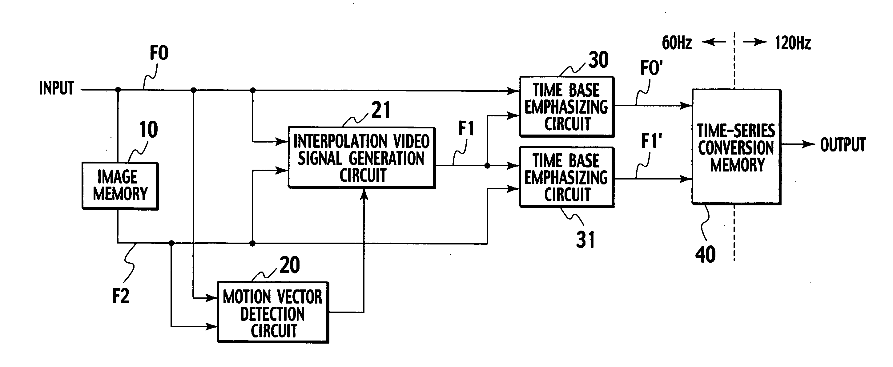
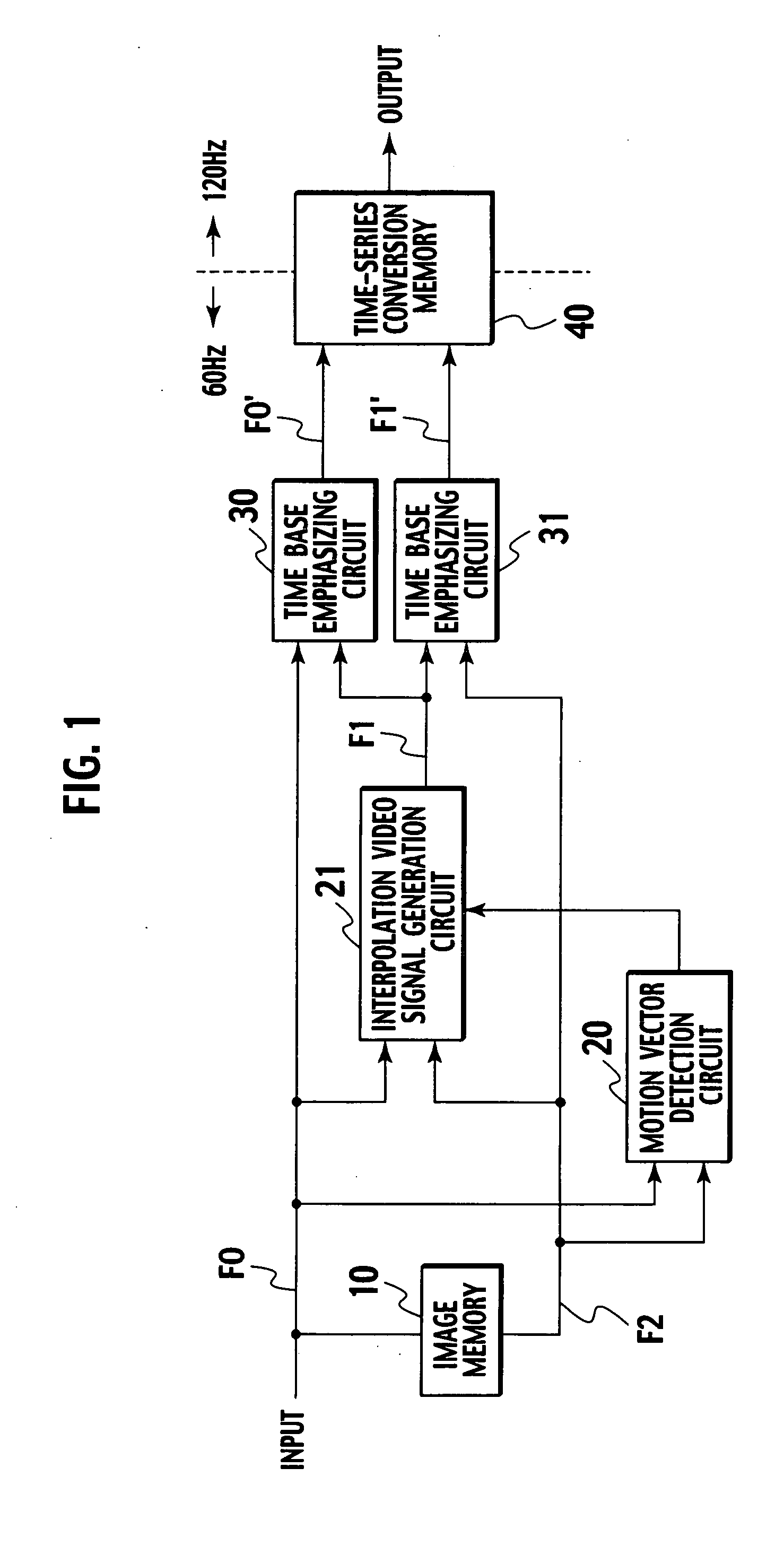
[0036]FIG. 1 is a block diagram showing an image display unit according to the present invention.

[0037] In FIG. 1, an input video signal F0 is supplied to an image memory 10, and this image memory 10 generates a one-frame delayed video signal F2. This input video signal F0 and the one-frame delayed video signal F2 are respectively supplied to a motion vector detection circuit 20 and an interpolation video signal generation circuit 21.

[0038] The motion vector detection circuit 20 detects a motion vector between frames based on the input video signal F0 and the one-frame delayed video signal F2 supplied thereto by using, e.g., a matching method, and supplies a detected vector to the interpolation video signal generation circuit 21.

[0039] The interpolation video signal generation circuit 21 generates an interpolation video signal F1 from the input video signal F0 and the one-frame delayed video signal F2 based on the motion vector supplied thereto. Further, the input video signal F0 ...

third embodiment

[0082] As described above, in the third embodiment, when time base emphasis is performed with respect to the input video signal F0, time base emphasis can be executed between two frames in conversion to 120 Hz. Furthermore, since this time base emphasis is carried out between two frames, a new frame memory does not have to be added.

[0083] Therefore, there are characteristics of suppressing an increase in cost while improving the moving image blur prevention effect as compared with the prior art. Moreover, since the processing is executed in a state where an operating frequency is 60 Hz, it is possible to avoid a difficulty in realization of a circuit operation due to an increase in the operating frequency.

[0084]FIG. 8 shows a fourth embodiment. A difference from the first embodiment lies in that the time base emphasizing circuit 31 shown in FIG. 1 is substituted by a time base emphasizing circuit 31′ to which not only the interpolation video signal F1 and the one-frame delayed vide...

fourth embodiment

[0093] As described above, in the fourth embodiment, when performing time base emphasis with respect to the interpolation video signal F1, time base emphasis can be carried out between preceding and subsequent frames in conversion to 120 Hz. Furthermore, a new frame memory does not have to be added in order to effect this time base emphasis between preceding and subsequent frames.

[0094] Therefore, this embodiment has characteristics that an increase in cost can be suppressed while improving a moving image prevention effect as compared with the prior art. Moreover, since the processing is carried out with an operating frequency of 60 Hz, it is possible to avoid a difficulty in realization of a circuit operation due to speeding up of the operating frequency.

[0095] Additionally, although not shown, the third embodiment can be combined with the fourth embodiment to perform time base emphasis with respect to the input video signal F0 by using the interpolation video signal F1 which is o...


PUM


Abstract

A motion vector detection circuit detects a motion vector from a video signal and a one-frame delayed video signal. An interpolation video signal generation circuit uses this detected motion vector to generate an interpolation video signal which is interpolated between frames. Further, two time base emphasizing circuits respectively use a video signal of a preceding frame to perform time base emphasis with respect to the video signal and the generated interpolation video signal. The video signal and the interpolation video signal subjected to time base emphasis are written in a time-series conversion memory. Furthermore, alternately reading the interpolation video signal and the video signal in the mentioned order with a frequency which is double a write frequency can obtain an output video signal having a doubled frame frequency.

Description

BACKGROUND OF THE INVENTION [0001] 1. Field of the Invention [0002] The present invention relates to a hold type image display unit as typified by a liquid crystal display unit, and more particularly, it relates to an image display unit which can reduce blurriness of a moving image. [0003] 2. Description of the Related Art [0004] As an image display units, there are an impulse type display unit which intensively emits light in a moment that an image is written like a display unit using a cathode ray tube (CRT) and a hold type display unit which holds display from writing of an image to writing of an image of a next frame like an active matrix type display unit having a memory function per each pixel. As the active matrix type display unit, there is a liquid crystal display unit using a thin film transistor (TFT). In the liquid crystal display unit, an image written in a pixel by a TFT and a capacitor arranged in accordance with each pixel is held for a fixed time. [0005] Since a res...

Claims


Application Information

Patent Timeline
Patent Type & Authority Applications(United States)
IPC IPC(8): G09G3/36
CPCG09G3/3611G09G2320/0247G09G2320/0252G09G2340/16G09G2320/0261G09G2320/106G09G2340/0435G09G2320/0257
Inventor AIBA, HIDEKI
Owner JVC KENWOOD CORP A CORP OF JAPAN
Why Eureka
Try Eureka