High-impedance attenuator

a high-impedance attenuator and circuit technology, applied in the field of high-impedance attenuator circuits, can solve the problems of filtering limiting the bandwidth of test equipment, inaccurate waveform rendering, parasitic capacitance introduction into the signal path, etc., to reduce parasitic capacitance, reduce the effective length of the probe lead, and increase the bandwidth of the test instrument

Active Publication Date: 2006-11-30
ANALOG DEVICES INC
View PDF11 Cites 47 Cited by
  • Summary
  • Abstract
  • Description
  • Claims
  • Application Information

AI Technical Summary

Benefits of technology

[0009] Such combinations of micromachined switches and attenuators can be included in the signal path of a test instrument, thus reducing parasitic capacitance and, thereby, increasing the bandwidth of the test instrument. Because the micromachined switches and attenuators are much smaller than prior art switches and electromechanical relays, the micromachined switches and attenuators can be included in test a equipment probe, along with integrated circuit signal processing components, such as an analog-to-digital (A / D) converter. Including attenuators and an A / D converter in a probe moves these components electrically closer to the signal under test and reduces the effective length of the probe lead.

Problems solved by technology

However, these switches and relays are large and, therefore, introduce large amounts of parasitic capacitance into the signal path.
This capacitance can distort the signal, thereby leading to inaccurate renderings of waveforms, etc.
This filter limits the bandwidth of the test equipment.
Electromechanical relays draw a significant amount of power.
In addition, mechanical switches and electromechanical relays can not be operated at high switching speeds.

Method used


Image

  • High-impedance attenuator
  • High-impedance attenuator
  • High-impedance attenuator

Examples


Embodiment Construction

[0050] The contents of U.S. Provisional Patent Application No. 60 / 681,598, filed May 17, 2005 and entitled “High Impedance Attenuator;” U.S. Provisional Patent Application No. 60 / 681,599, filed May 17, 2005 and entitled “Micro-Machined Switch / Relay Integrated with a Charge Pump” and U.S. Patent Application No. (not yet assigned), attorney docket number 2954 / 174, filed May 17, 2006 and entitled “Micromachined Transducer Integrated with a Charge Pump” are all hereby incorporated by reference.

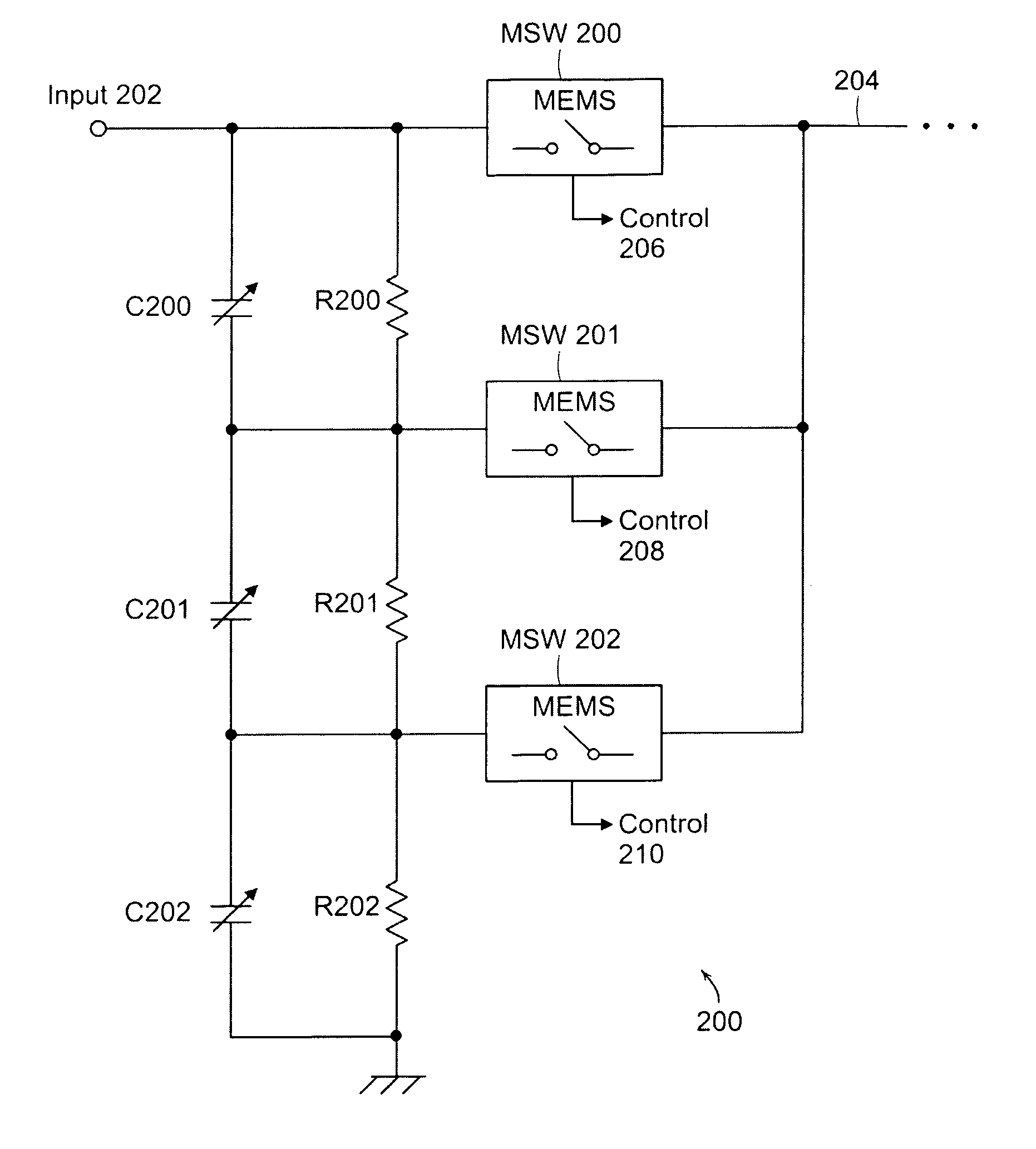
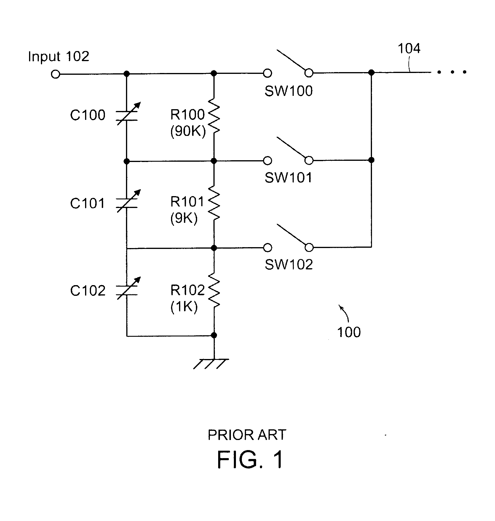
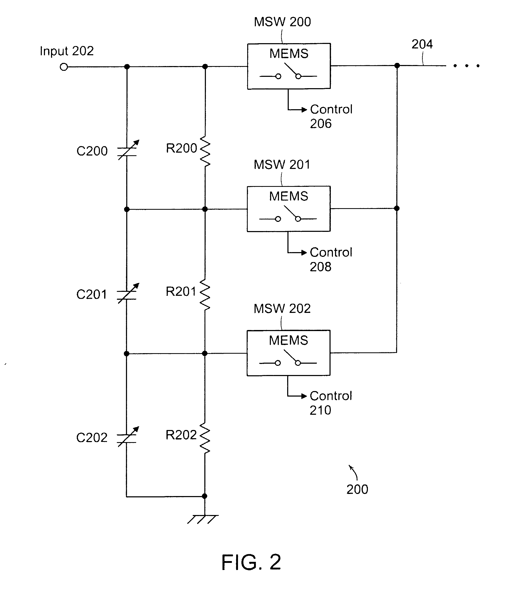
[0051] Attenuators, such as resistors, are commonly used in “front-end” circuits of test equipment to scale down the amplitude of input signals or in “back end” circuits of test equipment that generates signals. FIG. 1 is a schematic diagram of a typical prior art front end attenuator circuit 100 from, for example, an oscilloscope. An input signal is applied to an input node 102. An output 104 from the attenuator circuit 100 is provided to a subsequent stage (not shown). Resistors R100, R101 and ...


PUM


Abstract

One or more micromachined (MEMS) switches switch attenuators, such as resistors, into or out of a signal path, such as of a test instrument. The MEMS switches can be fabricated on the same substrate as the attenuators, or the switches or attenuators can be mounted on the same substrate as the others are fabricated. An instrument probe includes attenuators and MEMS switches that are controlled by the instrument and/or by a control circuit in the probe. Optionally, the probe includes reactive elements, such as capacitors, and MEMS switches to compensate for electrical characteristics of the probe and/or probe lead, and the probe or a test instrument automatically sets the MEMS switches to connect appropriate ones of the reactive elements to a signal path within the probe.

Description

CROSS REFERENCE TO RELATED APPLICATIONS [0001] This application claims priority of U.S. Provisional Patent Application No. 60 / 681,598, filed May 17, 2005 and entitled “High Impedance Attenuator” and U.S. Provisional Patent Application No. 60 / 681,599, filed May 17, 2005 and entitled Micro-Machined Switch / Relay Integrated with a Charge Pump.TECHNICAL FIELD OF BACKGROUND ART [0002] The present invention relates to high-impedance attenuator circuits and, more particularly, to such circuits that include micromachined switches or relays. [0003] Some test, laboratory and diagnostic equipment, such as oscilloscopes, digital multimeters, electrocardiograms and the like, receive electrical signals from devices or subjects under test and display or provide information about the signals. Other equipment, such as waveform generators, generate electrical signals for injection into circuits, subjects, etc. (Signal receiving and signal generating equipment is hereinafter collectively referred to as...

Claims


Application Information

Patent Timeline
Patent Type & Authority Applications(United States)
IPC IPC(8): G02B6/00
CPCH03H2007/006H03H7/24
Inventor FRAME, JAMESMETZLER, CRISPIN
Owner ANALOG DEVICES INC
Why Eureka
Try Eureka