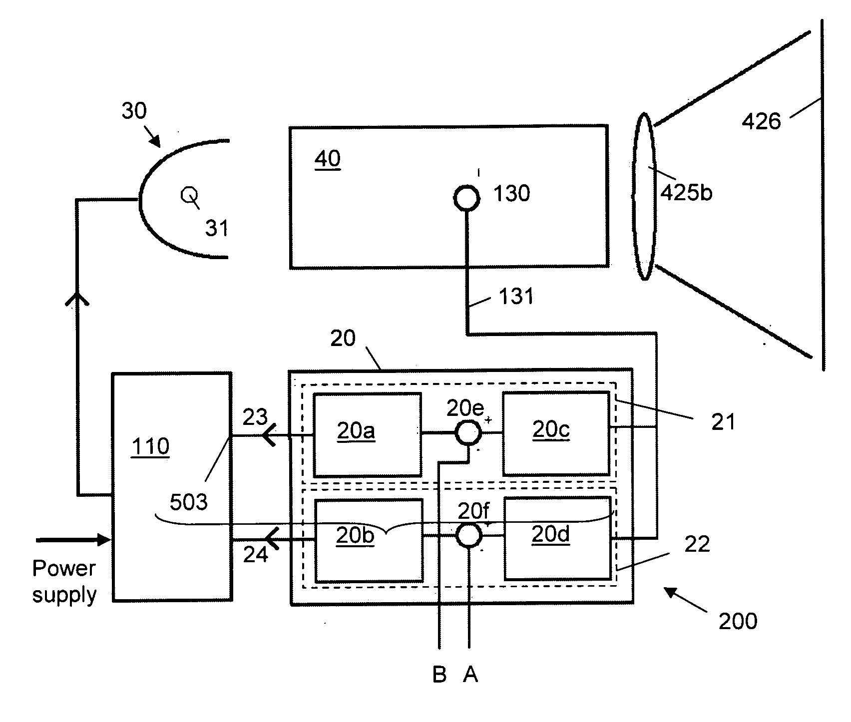
Projector lamp control for increased lamp life

Inactive Publication Date: 2006-12-07
BARCO NV
19 Cites 11 Cited by

AI-Extracted Technical Summary

Problems solved by technology

Therefore, the hot anode quickly burns back.
Thus, while AC lamps can be regenerated for thousands of hours, DC lamp electrodes are degrading quickly during lamp life.
The above difficulties with DC lamps have resulted in specialised DC designs being developed which differ significantly from AC designs.
However, this requires symmetrical electrodes.
Although it is known to compensate for loss of electrode material, no electronic ballast technique is k...

Method used

[0044] The embodiments of the present invention can increase lamp life by reducing the above phenomena or correcting for these, by keeping the light flux coupled into the illumination system constant or at least more constant over the lamp life and/or by reducing or eliminating the visibility of the arc displacements.
[0050] The controller 20 may furthermore comprise second compensation means 22 for generating a slow control signal 24 to compensate for slower changes in output level detected by the light sensor 130. The slower changes include changes which appear so slowly that they are not immediately visible by the human eye, e.g. degraded lamp intensity output due to ageing of the lamp.
[0065] As an option, the first compensation means 21 and/or the second compensation means 22, i.e. the fast and/or the slow control loop, can be equipped with an AGC (Automatic Gain Control), in order to extend the dynamic range of these control loops. This AGC of course needs to have a slow reaction speed, in order not to react on the fast disturbances.
[0079] One or more light sensors 130a, 130b is provided for each channel A, B, for example a fast and a slow light sensor 130a, 130b for each channel A, B. Fast and slow compensation feedback loops are provided for each channel A, B. An electrical signal 131a, 131b from the one or more light sensors 130a, 130b is provided to the respective feedback loops of the channels A, B. The fast feedback loop may get the sensor signal 131a, 131b from the sensor 130a, 130b respectively, and apply it to the respective power supplies 110 of the light sources lamp 1, lamp 2, lamp 3, lamp 4 in order to filter out fast changes in the light output of the respective light sources lamp 1, lamp 2, lamp 3, lamp 4. The slow feedback loop may get the sensor signal 131a, 131b from the sensor 130a, 130b respectively, and apply it to the respective power supplies 110 of the light sources lamp 1, lamp 2, lamp 3, lamp 4 in order to filter out slow changes in the light output of the respective light sources lamp 1, lamp 2, lamp 3, lamp 4. The slow feedback loop may include a processing means such a...

Benefits of technology

[0021] In a second aspect, the present invention provides a projector system with improved life time, the projector system having a lamp control system according to embodiments of the present invention. Embodiments of the present invention can be applied to front and to rear projectors.
[0022] In a third aspect, the present invention provides a method of extending life time o...

Abstract

An electronic lamp control system for life time extension of a DC high intensity discharge lamp has a light sensor (130) for sensing an output of a lamp (31), a power supply (110) for the lamp (31), and a controller (20) for controlling the power supply (110). The controller (20) has a high pass filter (20c) for compensating for a leading edge of a detected change in lamp power output caused by each arc displacement. Lamp life is extended since damage to the lamp electrodes by the arc displacements is reduced. The system can have multiple lamps for the same illumination area, or multiple channels for illuminating different areas, coupled to provide uniform illumination. The controller (20) can compare a sensed level to a reference, to output a level control signal, then add a correction signal from the high pass filter to the level control signal.

Application Domain

Electrical apparatusElectric light circuit arrangement +2

Technology Topic

High-pass filterEngineering +8

Image

  • Projector lamp control for increased lamp life
  • Projector lamp control for increased lamp life
  • Projector lamp control for increased lamp life

Examples

  • Experimental program(2)

Example

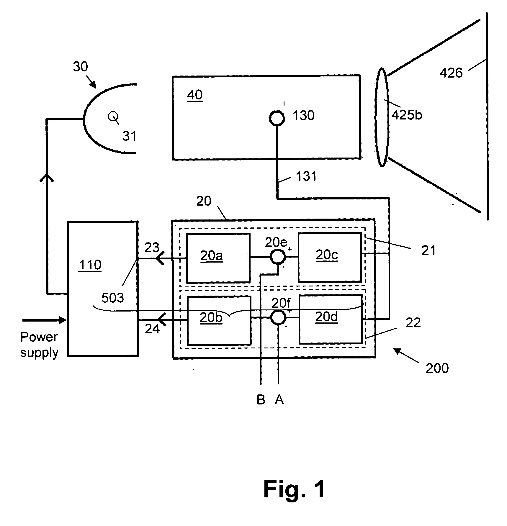
[0046]FIG. 1 illustrates a first embodiment of the present invention. This first embodiment of the present invention illustrates a lamp control system 200 of a projection device, for obtaining life extension of a DC discharge lamp, preferably a DC HID lamp. A DC lamp unit comprises at least one lamp-reflector assembly 30 comprising a high intensity discharge (HID) DC lamp 31 driven by a DC lamp power supply controller 110. The light flux of lamp-reflector assembly 30 is coupled into an illumination and modulation system 40. A light sensor 130 is positioned on a specific location in the illumination and modulation system 40 to provide an electrical signal 131 proportional to the total light flux of the lamp-reflector assembly 30. The location of the sensor 130 should be such that the detected light intensity is proportional to the average light intensity over the area of the display screen, and so that it is independent of the image content. This means that the light sensor 130 has to be positioned before the light modulator. The sensor may not be sensible to spectral variations in the light. Neither may it be sensible to wavelengths falling outside the wavelengths used for the illumination application, e.g. in case of a projector for visual light, the sensor may not react to IR fluctuations.
[0047] The electrical signal 131 from the light sensor 130 feeds a controller 20 having at least first compensation means 21 for edge compensation in the light flux of the lamp-reflector assembly 30 an in particular of the DC HID lamp 31. The first compensation means 21 generates a fast control signal 23 to quasi instantaneously or instantaneously compensate for edges in the light detected by the light sensor 130, which fast control signal 23 is fed to the lamp power supply controller 110. With “quasi instantaneously” is meant that the compensation is carried out faster than the temporal response of the human visual system.
[0048] The controller 20 preferably comprises a high pass filter 20c and a drive circuit 20a to drive the lamp power supply 110. The lamp power supply 110 delivers a controlled amount of power to the lamp 31, depending on a first reference A generated by a processing means (not illustrated in FIG. 1) and on the electrical signal 131.
[0049] The controller 20 compensates for edges in the light flux of the lamp-reflector assembly 30, and therefore corrects for the flicker appearing in DC HID lamps. Unexpectedly, this compensation seems to also positively influence the gradually changing light fall-off over life time. The combined result is that life time is extended much more than what could be expected.
[0050] The controller 20 may furthermore comprise second compensation means 22 for generating a slow control signal 24 to compensate for slower changes in output level detected by the light sensor 130. The slower changes include changes which appear so slowly that they are not immediately visible by the human eye, e.g. degraded lamp intensity output due to ageing of the lamp.
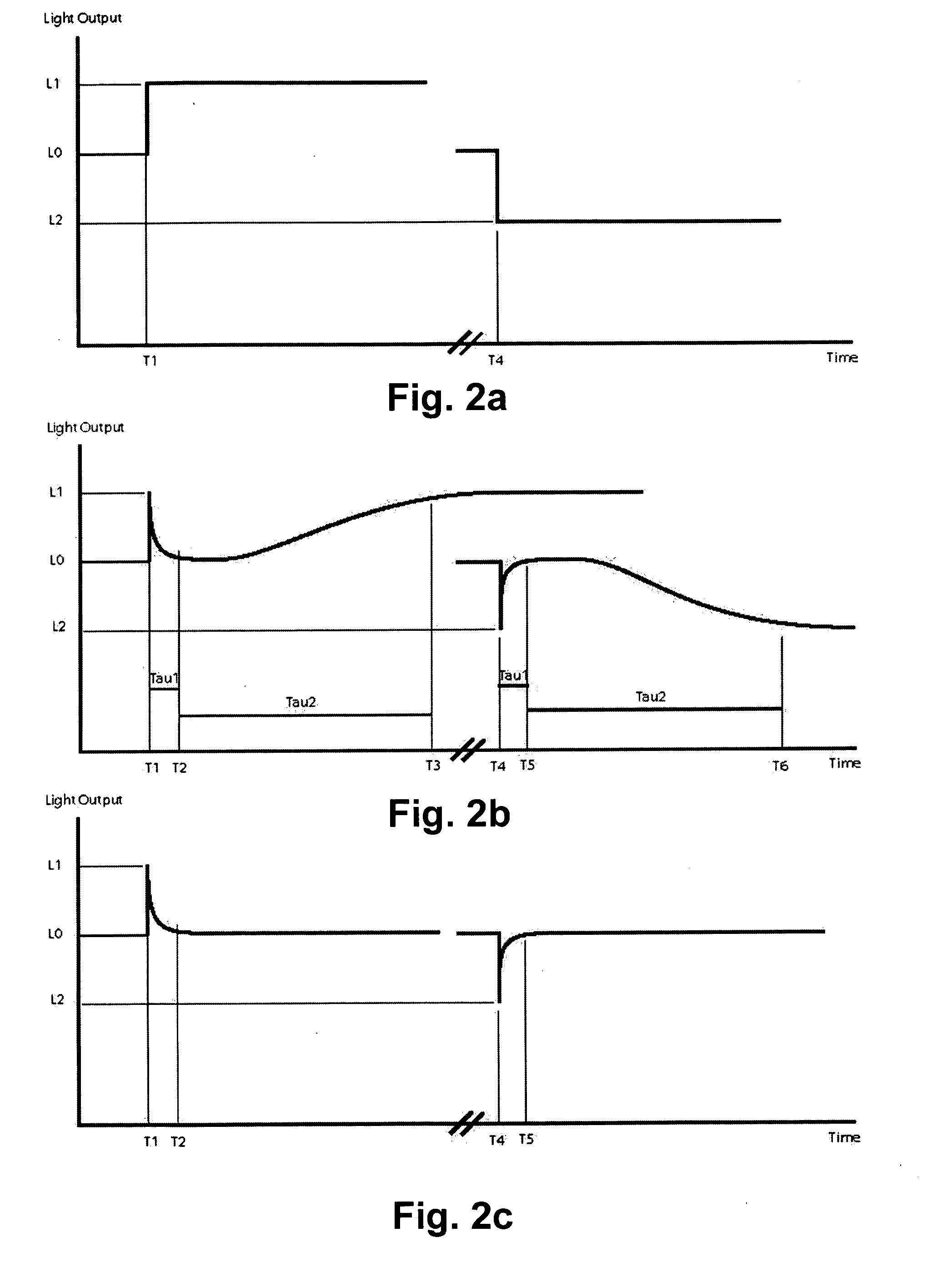
[0051] When the lamp-reflector assembly 30 and/or the illumination and modulation system 40 introduces a random disturbance, this will be detected by the light sensor 130, which generates a corresponding electrical signal 131. Through the high pass filter of the controller 20 this signal is returned to a processing means such as e.g. a differential amplifier, comparing this signal with a reference signal. The output of the controller 20 controls the lamp power supply 110 in order to achieve a constant light-flux on light sensor 130. The controlled light output in function of time, which is obtained with a system according to the first embodiment of the present invention, is illustrated in FIG. 2b.
[0052] As can be appreciated from FIG. 1, according to an embodiment of the present invention, in fact two compensation loops may be provided in the lamp control system 200: a fast compensation loop and a slow compensation loop.
[0053] The fast compensation AC coupled loop is provided in the lamp control system 200, comprising the lamp-reflector assembly 30 with the HID lamp 31 driven by the lamp power supply controller 110, the illumination and modulation system 40, the light sensor 130 and the first compensation means 21. The first compensation means 21 comprises a high pass filter 20c and a drive circuit 20a to drive the lamp power supply controller 110. The lamp power supply controller 110 delivers a controlled amount of power to the lamp 31, depending on a first reference A generated by a processing means (not illustrated in FIG. 1) and on the electrical signal 131.
[0054] When the lamp-reflector assembly 30 and/or the illumination and modulation system 40 introduces a random disturbance, this will be detected by the light sensor 130, which generates a corresponding electrical signal 131. Through the high pass filter 20c this signal is returned to a processing means such as e.g. a differential amplifier 20e, comparing this signal with a second reference signal B. The output of this processing means, e.g. differential amplifier 20e, controls the circuit 20a to drive the lamp power supply controller 110 in order to achieve a constant light-flux on light sensor 130.
[0055] Functions of the fast-compensation loop include compensating quasi instantaneously or instantaneously for edges of transient changes caused by arc displacements. As this is an AC coupled loop the correction will disappear after a while. During this time the slow control loop has to take over and keep the light-flux constant. An example is shown graphically in FIGS. 2a-2c. Light output of the lamp-reflector assembly 30 is shown versus time.
[0056] In parallel with the fast compensation loop, a slow compensation loop may be present, which is a DC coupled loop, comprising the lamp-reflector assembly 30 with the HID lamp 31 driven by the lamp power supply controller 110, the illumination and modulation system 40, the light sensor 130, and the second compensation means 22. The second compensation means 22 comprises a low pass filter 20d and a drive circuit 20b to drive the lamp power supply controller 110. The lamp power supply controller 110 delivers a controlled amount of power to the lamp 31, depending on a first reference A generated by a processing means (not illustrated in FIG. 1) and on the electrical signal 131.
[0057] In use, the lamp-reflector assembly 30 generates an amount of light-flux coupled into an optical system comprising the illumination and modulation system 40. This light-flux is measured with light sensor 130, which generates a corresponding electrical signal 131. Through the low pass filter 20d this electrical signal 131 is returned to a processing means such as e.g. a differential amplifier 20f, comparing this signal with the first reference signal A in an analog circuit e.g. comprising an active electronic element such as a comparative amplifier, or in a digital circuit e.g. comprising a processing element. The output of this processing means, e.g. amplifier 20f, controls the circuit 20b to drive the lamp power supply controller 110 in order to achieve a constant light-flux on the light sensor 130. The timing interval, i.e. the sampling frequency and therefore the correction frequency, by which the first reference A is changed in order to control the average light-output of the system, is defined by the processing means.
[0058] Functions of the slow-compensation loop include the following:
Compensating for slow variations over the lifetime of a lamp.
[0059] Compensating for tolerances in between different lamps when using a system with a plurality of lamps, e.g. for multi-channel systems having a plurality of lamps for projecting images on different areas of a display screen, or for multi-lamp systems having a plurality of lamps for projecting images on a same area of a display screen.
Compensating for a residual error after interaction of the fast-compensation loop (see below).
[0060] During operation the light coupled into the illumination and modulation system 40 of the projection display arrangement is expected to be at level L0 (see FIG. 2a). At time T1 there is an abrupt displacement of the arc in the light bulb of the HID lamp 31. This arc displacement will result in an abrupt change of the light coupled into the illumination and modulation system 40 to a value L1. Without the feedback control system according to the present invention this would result to a noticeable change of the illumination on the display screen 426 if the displacement of the arc is sufficiently large in amplitude. Illumination changes of ˜1% in amplitude are noticeable by the human visual system if the frequency is <50 to 60 Hz.
[0061] With the electro-optical feedback control system according to the first embodiment of the present invention the light sensor 130 detects this abrupt light flux change and produces an electrical signal 131 proportional to the quasi instantaneously changing light intensity on the light sensor 130 (the light intensity on the light sensor 130 is proportional to the total light flux coupled into the illumination and modulation system 40). The switching time of a light sensor is typical ˜20 ns. This electrical signal 131 is fed back to the lamp power supply controller 110 through the high pass filter 20c of the first compensation means 21, and will result in a fast change (with time constant τ1) of the power applied to the HID lamp 31 and thus an elimination of the light flux change in the illumination and modulation system 40 if the loop gain of the feedback system is sufficiently large and stable. This light flux change, shown by the peak in FIG. 2c will not be noticeable if the control loop comprising the first compensation means 21 reacts faster (e.g. <10 ms range) than the temporal response of the human visual systems. Because of the slow feedback loop comprising the second compensation means 22, the lamp power will be restored to its original value L0 with a time constant τ2>>τ1. This will result in a very slow light flux variation which is not noticeable by the human visual system.
[0062]FIG. 2c shows that the control system 200 comprising the first compensation means 21 and the second compensation means 22 can keep the light output at L0, between times T2 and T3.
[0063]FIG. 2b shows another curve gradually increasing during the time between T2 and T3. This is the light output if the second compensation means 22, i.e. the proportional slow feedback loop, is not active to maintain the correct level L0 over longer periods, i.e. when only the instantaneous changes are filtered out by the first compensation means 21, i.e. the fast feedback loop. In that case, the light output will evolve towards L1 as can be seen from FIG. 2b.
[0064] At T4, another similar event is shown, but the arc displacement results in a drop of the light output. The control system 200 with the first and the second compensation means 21, 22, i.e. the fast and the slow loop, reacts to maintain the light output at L0, as illustrated in FIG. 4c. The control system with only the fast loop would react to maintain the light output at L1, as illustrated in FIG. 4b.
[0065] As an option, the first compensation means 21 and/or the second compensation means 22, i.e. the fast and/or the slow control loop, can be equipped with an AGC (Automatic Gain Control), in order to extend the dynamic range of these control loops. This AGC of course needs to have a slow reaction speed, in order not to react on the fast disturbances.
[0066] The light sensor 130 as used in the first embodiment of the present invention may be part of a sensor circuit, e.g. as illustrated in FIGS. 3a and 3b. An exemplary sensor circuit for use in the embodiment of FIG. 1 will now be described. This circuit can be implemented using two different sensors for slow and fast correction. Alternatively (not illustrated in FIGS. 3a and 3b), a single light sensor 130 could be used for both the fast and the slow feedback loop. FIGS. 3a and 3b illustrate a sensor circuit with separate sensors 132, 133 for the fast and the slow feedback loop.
[0067] As illustrated in FIG. 3a, a first light sensing element 132, such as e.g. a PIN photodiode, may be used as the brightness sensor for the fast feedback loop comprising the first compensation means 21. The electrical signal 131 a from the first light sensing element 132 is amplified by an amplifying element 400, typically by an opamp. A buffer circuit 401, e.g. using another opamp 402 having its output fed back to its negative input terminal, is coupled between the amplifying element 400 and the node 403 to the first compensation means 21. The buffered signal is then fed to the controller 20, more particularly to the first compensation means 21 thereof. Buffering can be used to lower the impedance of the signal for sending it to the first compensation means 21 described below.
[0068] A second light sensing element 133, the slow sensor, may e.g. be implemented as a light to frequency converter 404, as illustrated in FIG. 3b, or as any other suitable light to signal converter. The light to frequency converter 404 may e.g. be component TSL235R which can be obtained from Texas Advanced Optoelectronic solutions or component TSL230 which can be obtained from Texas Instruments. Its output is a signal which is frequency dependent on the received amount of light. This frequency is processed in a processing means 405 such as e.g. a microcontroller or a programmable digital logic device such as a Programmable Array Logic (PAL), a Programmable Logic Array, a Programmable Gate Array, especially a Field Programmable Gate Array (FPGA), to be then transferred, for example digitally transferred, to the controller 20, more particularly to the second compensation means 22 thereof.
[0069] The first light sensing element 132 and the second light sensing element 133 may physically be one and the same element, in which case the light sensing element needs to be a fast sensor, such as e.g. a PIN photodiode.
[0070] The first compensation means 21, part of the controller 20, provides edge compensation. An exemplary block-schematic illustration is given in FIG. 4.
[0071] The signal 406 that is coming from the light sensor 131, in particular from the fast light sensor 132, is sent to the high pass filter 20c built around a resistor R and a capacitor C.
[0072] The high pass filter 20c is coupled to a first buffer 501, the output of which is coupled to a first switch S1. Switch S1 is open in non-operational mode of the first compensation means, while a second switch S2 is closed in this situation.
[0073] A second buffer 502 brings a DC voltage at the capacitor C of the high pass filter 20c at the same level as the input 503 of the lamp power supply controller 110. This is needed to prevent that any current would flow between the first compensation means 21 and the lamp power supply controller 110 when the circuit is switched on. Not preventing this current flow could result in an abnormal output power to the lamp 31, which is not allowed. By providing this buffering circuit with the second buffer 502 the switching can occur smoothly with no visible effect on the light output. The analog switches S1 and S2 can be controlled by control means such as e.g. transistors, and can be driven e.g. by a digital output from a controller, which can be a local processor or any other processor available in the lamp control system 200 (not illustrated in FIG. 1).
[0074] When the compensation circuit, and thus the controller 20, is active, the second switch S2 is opened and the first switch S1 is closed. The high pass filter 20c is now between the light sensor 130 and the lamp power supply controller 110. Fast variations in light output are compensated for, while slow variations are not coming through, as they are being blocked by the high pass filter 20c. They are compensated for in the slow compensation circuit 22, which may be a digital compensation circuit.
[0075] In the above-described first embodiment of the present invention, a lamp control system 200 for a single DC lamp 31 is illustrated. According to the present invention, a plurality of DC lamps 31 and lamp-reflector assemblies 30 may be provided for illuminating a same area, e.g. on a projection screen 426. This is what is called a multi-lamp system. A single light sensor 130 associated with the plurality of lamp-reflector assemblies 30 may be provided for sensing the light emitted by the plurality of DC lamps 31. Alternatively, a plurality of light sensors 130 may be provided, for example a light sensor 130 being associated with each DC lamp 31, or even a plurality of light sensors being associated with each DC lamp 31. Each DC lamp may be provided with a separate power supply controller 110. 3. The controller 20 may be arranged so that the first compensation means 21 provides the edge compensation for each DC lamp 31 separately, while the second compensation means 22 provides the level control part common to more than one of the DC lamps 31.

Example

[0076] According to a second embodiment of the present invention, a multi-channel system is provided. An illustrative example of such multi-channel system is illustrated in FIG. 5. In a multi-channel system, a plurality of DC lamps are provided for illuminating different areas.
[0077] In a multi-channel projector system it is desirable to have all the projection devices in this system at the same output luminance level. This means the light-output of each projection device is equal if the illuminated area and the screen characteristics of all projection devices are identical. With a suitable communication system between the individual projection devices, the information of the light output levels can be exchanged between the projection device and adjusted to an equal luminance level.
[0078]FIG. 5 schematically shows an example of a multi-channel system with two channels A and B, however, this can be extended to any m×n configuration of illumination devices, e.g. projection devices such as rear and/or front projectors. As shown, each channel can have one or multiple light sources. In the embodiment illustrated in FIG. 5, the first channel A comprises three light sources, lamp 1, lamp 2 and lamp 3, and the second channel B comprises a single light source, lamp 4, each light source having a DC or AC power supply 110.
[0079] One or more light sensors 130a, 130b is provided for each channel A, B, for example a fast and a slow light sensor 130a, 130b for each channel A, B. Fast and slow compensation feedback loops are provided for each channel A, B. An electrical signal 131a, 131b from the one or more light sensors 130a, 130b is provided to the respective feedback loops of the channels A, B. The fast feedback loop may get the sensor signal 131a, 131b from the sensor 130a, 130b respectively, and apply it to the respective power supplies 110 of the light sources lamp 1, lamp 2, lamp 3, lamp 4 in order to filter out fast changes in the light output of the respective light sources lamp 1, lamp 2, lamp 3, lamp 4. The slow feedback loop may get the sensor signal 131a, 131b from the sensor 130a, 130b respectively, and apply it to the respective power supplies 110 of the light sources lamp 1, lamp 2, lamp 3, lamp 4 in order to filter out slow changes in the light output of the respective light sources lamp 1, lamp 2, lamp 3, lamp 4. The slow feedback loop may include a processing means such as processor A, processor B for each channel A, B, which processing means have the intelligence to adjust the light-flux for its own channel A, B in accordance with the light flux of the other channels. The processing means may for instance be a microcomputer, a programmable digital logic device such as a Programmable Array Logic (PAL), a Programmable Logic Array, a Programmable Gate Array, especially a Field Programmable Gate Array (FPGA). A communications link between each processing means processor A, processor B may be provided, such as an I2C link for example. An alternative (not illustrated in the drawings) is to have a single master control unit that will act as a master to control the different needed light-outputs of the individual light emitting devices such as e.g. projection devices.
[0080] By linking the channels A, B between each other, as illustrated in FIG. 5, the following difficulties in multi-channel systems can be avoided or reduced:
[0081] Replacing one lamp in the system. If the system is not linked this would mean the new lamp/projection device will have a much higher light-output compared to the others in the system. Due to the communication and adjustment process, the light-output of the projection device with the replaced lamp will be reduced to the same light-output as the others in the system.
Compensating for the differential aging of the lamps with the communication and adjustment method: in time one lamp will age faster than another. If the projection devices are linked all projector outputs are reducing with age at the same rate.
[0082] The fast compensation loop is compensating of course for arc-instability for each of the projectors individually.
[0083] In case an individual projection device has more than one lamp the fast and the slow loop may be fed back to all supplies separately. Alternatively, the fast loop may be fed back to all supplies separately, and the slow loop may be common to more than one of the lamps.
[0084] The lamps used with embodiments of the present invention can include the following examples:
Osram XBO 2200W/HP (Xenon—DC-lamp)
Osram XBP 1200W/HP (Xenon—DC-lamp)
Ushio PXL-20BA (Xenon—DC-lamp)
Ushio NSH30OW (Mercury—DC-lamp).
[0085] It has been found surprisingly that the lifetime of the HID DC light sources is increased by a factor of at least about 2 to 2.5 with respect to rated lamp life. This is illustrated in FIGS. 6a to 6d. FIG. 6a illustrates light output of a DC lamp in function of time without the compensation circuit of the present invention being present. It can be seen that after about 580 hours the light output drops below 60%. Flicker becomes unacceptable when its level becomes >1.5%. This value is reached at about 500 hours of on time, as illustrated in FIG. 6b. FIG. 6c illustrates the light output of a same DC lamp in function of time, with the fast and the slow compensation circuits of embodiments of the present invention being present. It can be seen that the light output drops below 60% only after about 1300 hours. Flicker becomes unacceptable because its level reaches more than 1.5% only after 1600 hours of operation time (FIG. 6d).
[0086] In view of the above, a DC lamp replacement policy can be set up, according to which DC lamps are replaced at their end of life time, the end of life time being determined by a method according to embodiments of the present invention. As the methods according to embodiments of the present invention extend the lifetime of the DC lamps, DC lamps controlled in accordance with embodiments of the present invention will have to be replaced less often than lamps driven in conventional ways.
[0087] It is to be understood that although preferred embodiments, and specific constructions and configurations have been discussed herein for devices according to the present invention, various changes or modifications in form and detail may be made without departing from the scope and spirit of this invention. For example, although described for projector applications, clearly the lamp control for extending lamp life can be applied to any other type of lighting using such lamps. As described above, a lamp control for a DC high intensity discharge lamp has a light sensor for sensing an output of the lamp, a power supply for the lamp, and a controller for controlling the power supply, having a high pass filter for compensating for a leading edge of a detected change in lamp power output caused by each arc displacement. Lamp life can be extended since damage to the lamp electrodes by the arc displacements is reduced. The system can have multiple lamps for the same illumination area, or multiple channels for illuminating different areas, coupled to provide uniform illumination. The controller can compare a sensed level to a reference, to output a level control signal, then add a correction signal from the high pass filter to the level control signal. Other variations can be conceived within the scope of the claims.

PUM

no PUM

Description & Claims & Application Information

We can also present the details of the Description, Claims and Application information to help users get a comprehensive understanding of the technical details of the patent, such as background art, summary of invention, brief description of drawings, description of embodiments, and other original content. On the other hand, users can also determine the specific scope of protection of the technology through the list of claims; as well as understand the changes in the life cycle of the technology with the presentation of the patent timeline. Login to view more.

Similar technology patents

Monitoring and adjusting memory usage in connected device systems

InactiveUS20200073579A1improve memory usageimprovement of lifetime characteristic
Owner:SIGNIFY HOLDING B V

Diamond coated tool

InactiveUS20140341664A1improvement of lifetime characteristicimproves defect resistance
Owner:SUMITOMO ELECTRIC HARDMETAL CORP

Band saw cutting apparatus and ingot cutting method

ActiveUS20110126814A1improved yieldimprovement of lifetime characteristic
Owner:SHIN-ETSU HANDOTAI CO LTD

Non-aqueous ink compositions containing transition metal complexes, and uses thereof in organic electronics

ActiveUS20190023930A1reduce operating voltageimprovement of lifetime characteristic
Owner:NISSAN CHEM IND LTD

Internal combustion engine ignition apparatus

ActiveUS20180306162A1improvement of lifetime characteristicdeterioration of combustion
Owner:MITSUBISHI ELECTRIC CORP

Classification and recommendation of technical efficacy words

  • extension of lifetime of product
  • improvement of lifetime characteristic

Electric fan system for vehicle

InactiveUS20060120903A1reduce unevennessextension of lifetime of product
Owner:DENSO CORP

Redox polymer based reference electrodes having an extended lifetime for use in long term amperometric sensors

InactiveUS20090294307A1considerable stabilityextension of lifetime of product
Owner:ABBOTT DIABETES CARE INC

Eyeglasses

ActiveUS20130321757A1improve use efficiencyextension of lifetime of product
Owner:CHEN LIN YUN

Method and system for controlling charge and discharge amounts of a main battery for a hybrid car

InactiveUS20070284158A1improve fuel economyextension of lifetime of product
Owner:HYUNDAI MOTOR CO LTD

Memory controller, nonvolatile storage module, access module and nonvolatile storage system

ActiveUS20110197034A1extension of lifetime of producteasily detect
Owner:SK HYNIX INC

Piezoceramic-based smart aggregate for unified performance monitoring of concrete structures

ActiveUS20080034884A1improvement of lifetime characteristic
Owner:UNIV HOUSTON SYST

Organic additives for improved lifetimes in organic and solution processible electronic devices

InactiveUS20120049120A1improvement of lifetime characteristicefficiently react
Owner:SUMITOMO CHEM CO LTD

Improving Storage Lifetime Using Data Swapping

InactiveUS20130254511A1reduce numberimprovement of lifetime characteristic
Owner:OPTIS CIRCUIT TECH LLC

Novel organic electroluminescent compounds and organic electroluminescent device using the same

InactiveUS20090295281A1excellent luminous efficiencyimprovement of lifetime characteristic
Owner:GRACEL DISPLAY INC

Apparatus and Process For Cooling Hot Gas

ActiveUS20080149316A1improvement of lifetime characteristicimprove reliability
Owner:SHELL USA INC
Why Eureka
Try Eureka