Optical subassembly of optical transceiver

Inactive Publication Date: 2006-12-07
NAT TAIWAN UNIV
View PDF5 Cites 22 Cited by
  • Summary
  • Abstract
  • Description
  • Claims
  • Application Information

AI Technical Summary

Benefits of technology

[0015] Thus, an objective of the present invention is to provide an optical transceiver module featuring both passive alignment and active alignment so that poor alignment pr

Problems solved by technology

Conventionally, high speed transmissions up to 10 Gb/sec, 40 Gb/sec, or even higher, is realized by increasing the operation frequency of the transmitter driver circuit, which inevitably leads to a significant increase of manufacturing costs.
All these add to the manufacturing costs, as well as power consumption.
Also, using laser diodes with lower transmission speeds makes the design for the electrical subassembly (ESA) and driver circuit less critical, but the more challenging part is the design of the optical subassembly (OSA), which is to combine optical signals of different wavelengths and couple them onto a single optical fiber (the part of TOSA), or to separate multiplexed optical signals on the

Method used


Image

  • Optical subassembly of optical transceiver
  • Optical subassembly of optical transceiver
  • Optical subassembly of optical transceiver

Examples


Embodiment Construction

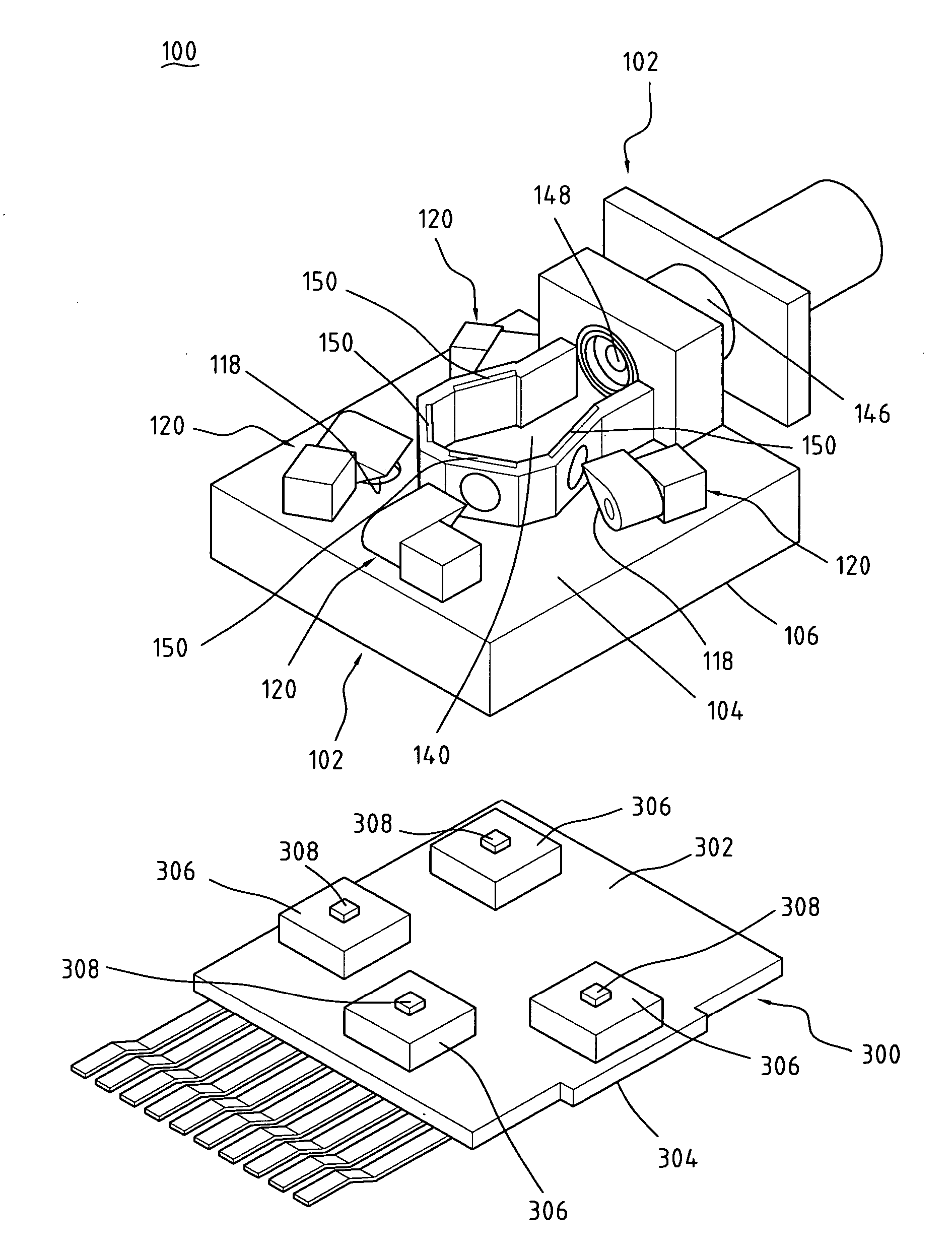
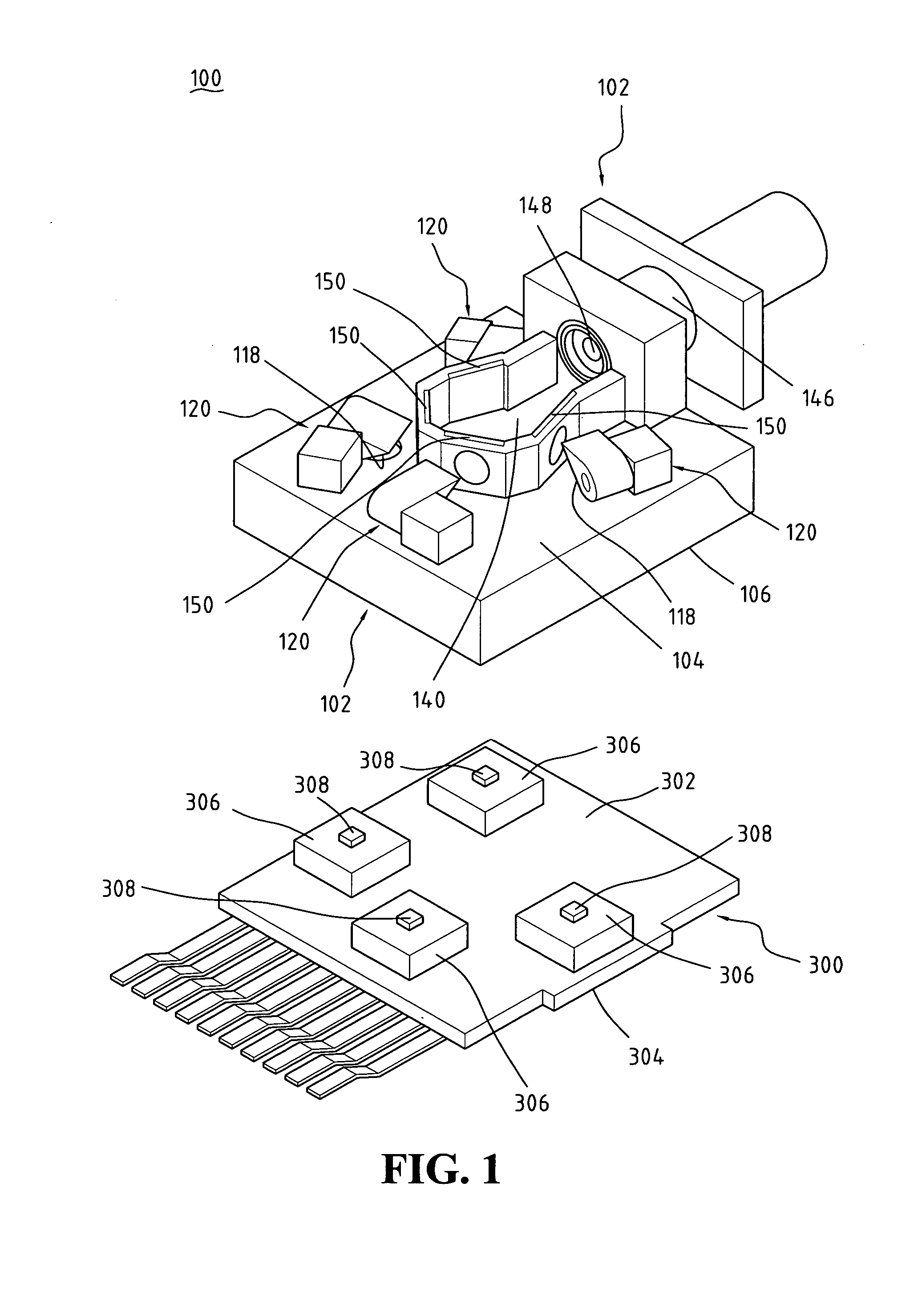
[0026] A preferred embodiment of the present invention will be described with reference to the attached drawings for explanation of the structure and function of an optical subassembly constructed in accordance with the present invention. It is, however, noted that the optical subassembly of the present invention can be embodied in both an optical transmitter module and an optical receiver module and an optical module that simultaneously comprises an optical transmitter module and an optical receiver module, such as an optical transceiver module. In the following, a description with respect to an optical receiver module will be given first.

[0027] With reference to the drawings and in particular to FIG. 1, which shows an exploded view of an optical subassembly constructed in accordance with the present invention embodied in an optical transmitter module, which is broadly designated with reference numeral 100, the optical transmitter module 100 comprises a body 102 having top and bot...


PUM


Abstract

A transceiver module comprised of a multiplexing/demultiplexing optical subassembly is provided. The optical subassembly includes either a transmitter module or a receiver module or both. The transmitter module has laser diodes emitting optical signals, which are reflected by reflectors, and coupled together by thin film filter. The receiver module includes thin film filters that decouple a received optical signal into constituent components. These components are reflected by reflectors to photo detectors by which the optical signals are converted into electrical signals. The reflector are capable of dual axis adjustment for adjustment of inclination thereof to effect active alignment. Further, the transmitter module and the receiver module define positioning recesses to position the laser diodes and photo detectors. The recesses are sized in accordance with the wavelengths associated with the laser diodes and photo detectors to effect passive alignment.

Description

BACKGROUND OF THE INVENTION [0001] 1. Field of the Invention [0002] The present invention relates generally to an optical transceiver module, and in particular to an optical subassembly of the optical transceiver module, featuring small size, high precision alignment, and excellent coupling efficiency. [0003] 2. The Prior Arts [0004] Optical fiber transmission is instrumental in the development of many advanced applications for telecommunications and data communications. This high bandwidth transmission needs local fiber access to provide two-way communications to the home through an optical transceiver, which is composed of a driver circuit, an electrical subassembly (ESA), and an optical subassembly (OSA). Operation frequency plays a critical role in determining the transmission speed. Conventionally, high speed transmissions up to 10 Gb / sec, 40 Gb / sec, or even higher, is realized by increasing the operation frequency of the transmitter driver circuit, which inevitably leads to a ...

Claims


Application Information

Patent Timeline
IPC IPC(8): G02B6/42
CPCG02B6/29361G02B6/4246G02B6/4214
Inventor WU, ENBOASHIH, YING-CHING
Owner NAT TAIWAN UNIV
Why Eureka
Try Eureka