Toner for electrostatic development, developer, image forming method, image-forming apparatus and process for cartridge using the same

a technology for electrostatic development and image forming, which is applied in the direction of electrographic process, electrographic process using charge pattern, instruments, etc., can solve the problems of constant quality of images, maintenance and size reduction of apparatus, and difficult to obtain, so as to achieve effective and uniform operation, excellent image stability, and the effect of not deteriorating the operating life of the photoconductors

Inactive Publication Date: 2006-12-07
RICOH KK
View PDF7 Cites 119 Cited by
  • Summary
  • Abstract
  • Description
  • Claims
  • Application Information

AI Technical Summary

Benefits of technology

[0038] Secondary, an object of the present invention is to provide a toner for electrostatic development with which background smear does not occur and toner leakage of supplied toner caused by reset defects, which are induced from an excessive charge of toner on the developing roller, and streaks on the transported surface due to electrostatic aggregation are suppressed, and is capable of obtaining excellent image stability by performing friction charging between developing roller and developer layer thickness control member in the development apparatus effectively and uniformly.
[0039] Thirdly, an object of the present invention is to provide a toner composition for electrostatic development with which image defects such as image deletion caused by charge defects of photoconductors does not occur and operating life of the photoconductors are not deteriorated by preventing occurrence of filming and scratches on the photoconductors by using additives of appropriate hardness.
[0040] Forthly, an object of the present invention is to provide a nonmagnetic one-component image forming method and process cartridge with which background smear does not occur and toner leakage of supplied toner caused by reset defects, which are induced from an excessive charge of toner on the developing roller, and streaks on the transported surface due to electrostatic aggregation are suppressed and are capable of obtaining excellent image stability by performing friction charging between developing roller and developer layer thickness control member in the development apparatus effectively and uniformly wherein the composition of a thin layer forming material in the development apparatus is a combination of metal and resin.
[0041] Fifthly, an object of the present invention is to provide an image forming method and process cartridge with which degradation of resistance in charging member does not occur and charging performance is not deteriorated even when the contact member is contaminated with a composition in which the latent electrostatic image bearing member is charged by a contact method.

Problems solved by technology

However, since carrier deterioration and fluctuation of mixing ratio of toner and carrier are likely to occur, a constant quality of images in a prolonged period is difficult to obtain and there are drawbacks in maintenance and size reduction of apparatus, making single component developer method more advantageous in these points.
However, this does not stabilize electrification property of the toner.
However, only equivalent effect compared to the toner in which silica and alumina are added separately can be obtained and when the ratio of alumina is large, there are problems of fog, electrification property and environmentally-resistant durability in particular.
Being small in particle diameter is also disadvantageous in obtaining above effects and the effects on member and carrier contamination and condition change of external additives on the toner surface are also small.
However, the charged amount of the toner in the two-component developer method could not be uniformized sufficiently by these methods disclosed in prior art.
The single component developer method is relatively easy to employ because of its simple and compact design as a developing system which is not carrier-mediated, however, it is disadvantageous in terms of printing speed or long-life and therefore, it is useful as a compact printer in a low-speed region with which user maintenance and exchanges are easy.
When the charge-up phenomenon occurs, it is unlikely that the toner in the upper portion of the toner layer formed on the developing sleeve is charged, decreasing the charged amount of toner and therefore, it is likely to result in background smear, toner leakage and toner dispersal in nonimage portions.
Various treating agents are used to settle above issues, however, they also pose problems.
In JP-A No. 2002-31913, for example, silicate magnesium minerals (attapulgite and cepiorite) have a high moisture content and charge defects are likely to occur even in a normal usage environment and the problems caused by charge defects such as background smear, toner leakage and toner dispersal are likely to occur.
Moreover, since they have low Mohs hardness, filming on the photoconductors is likely to occur, leading to image defects such as image deletion.
Moreover, when silicone oil-treated silicate magnesium as disclosed in JP-A No. 3-294864 and JP-A No. 4-214568 is used, the deterioration of toner flowability and increase in amount of charge caused by silicone oil are induced leading to transport defects and density degradation in the development apparatus.
However, when a toner with a coating ratio of 60% to 100% is prepared by using silicate magnesium as a silicate fine powder, an oppositely charged toner is likely to occur, causing background smear if it is used as a negatively charged toner.
And when a titanic acid fine powder is used as a toner disclosed in JP-A No. 11-184239, the material itself has low resistance and the charge leakage is large and likely to cause background smear, toner leakage and toner dispersal.
Moreover, since titanic acid fine powder is likely to separate from the toner, when contact charging method is employed, the contact charging member is contaminated, charge defects of the latent electrostatic image bearing member is induced leading to image defects.
When titania is used as toner as disclosed in JP-A No. 2003-186240, since this material also has low resistance and high permittivity, adjustment of the content is difficult, and when a large amount is used, the charge leakage also becomes large leading to charge deterioration of the entire toner and when a small amount is used, charged amount is increased.
In either cases, background smear, toner leakage and toner dispersal are likely to occur.
And at the same time, when titania of relatively large particle diameter is used, it is likely to separate from the toner, and when a contact charging method is employed, the contact charging member is contaminated, the charge defects of the latent electrostatic image bearing member is induced leading to image defects.
Furthermore, the charged amount of the toner in single component developer method could not be sufficiently uniformized by the methods disclosed in JP-A Nos. 2002-31913, 3-294864, 4-214568, 11-95480, 11-184239, 2003-186240 and “Journal of the Imaging Society of Japan” vol.

Method used


Image

  • Toner for electrostatic development, developer, image forming method, image-forming apparatus and process for cartridge using the same
  • Toner for electrostatic development, developer, image forming method, image-forming apparatus and process for cartridge using the same
  • Toner for electrostatic development, developer, image forming method, image-forming apparatus and process for cartridge using the same

Examples


example 1

[0219] 0.4 parts by mass of inorganic oxide, forsterite (first inorganic fine particle) as shown in Table 1 and 1 part by mass of Silica RX200 (second inorganic fine particle) were added to 100 parts by mass of colored resin particle A and mixed by means of a Henschel mixer at a peripheral velocity of 40 m / sec. for 60 seconds to obtain a magenta toner 1.

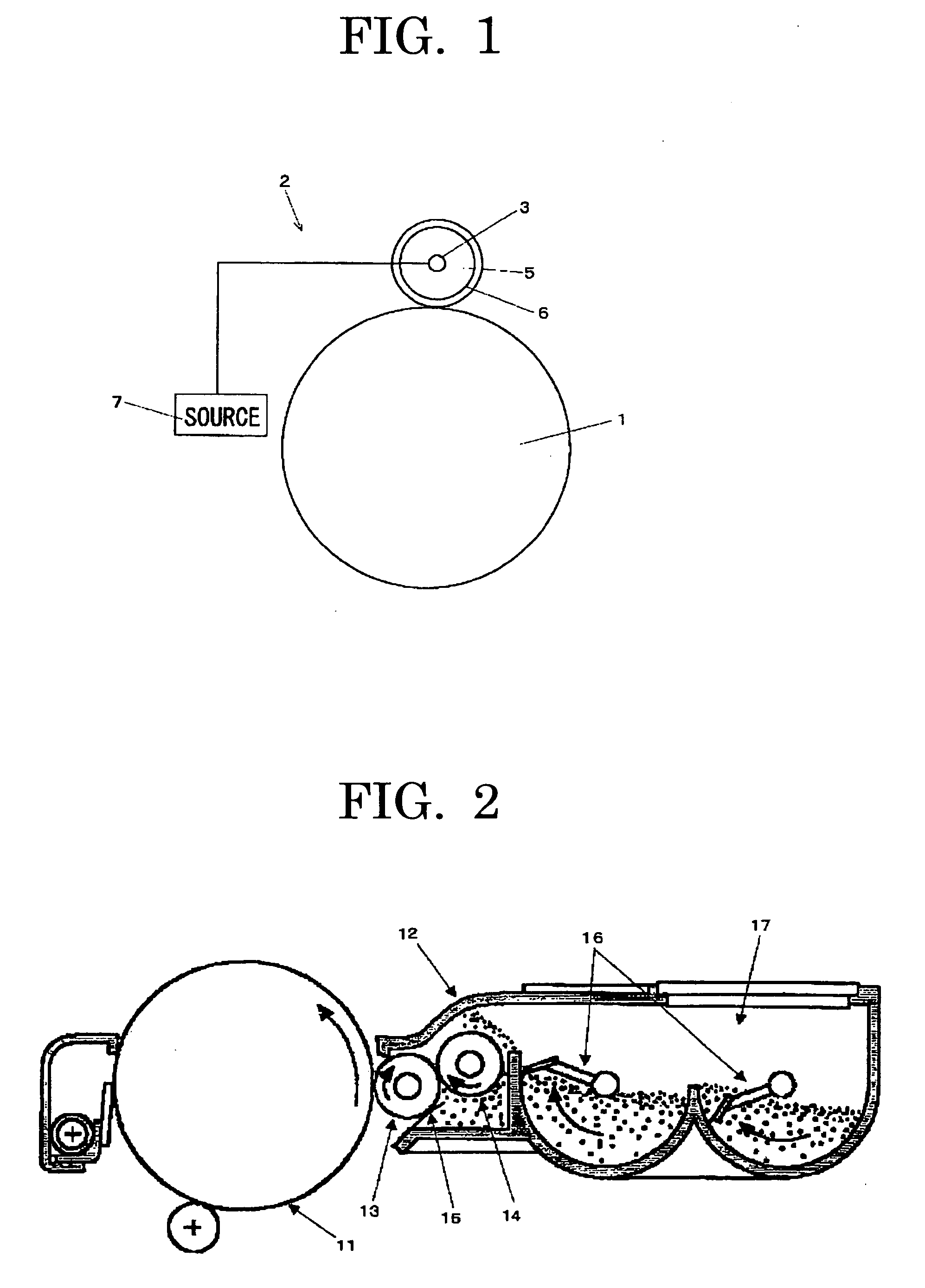
[0220] 2,000 sheets of a specific print pattern at a printing ratio of 6% were repeatedly copied under N / N environment (23° C., 45%), using the above magenta toner as single component developer and an image forming apparatus (IPSiO CX2500 manufactured by Ricoh Company, Ltd.). The condition of developing roller in the development apparatus, copied image and filming and scratch on the photoconductor were visually observed and evaluated. The results are shown in FIG. 1.

[0221] The evaluation standard is as follow. [0222] A: good [0223] B: poses no problem for practical use [0224] C: no good for practical use

example 10

[0227] 1.5 parts by mass of inorganic oxide 1, forsterite (first inorganic fine particle) as shown in Table 3 and an external additive 1 as shown in Table 3 were added to 100 parts by mass of the toner particle B and mixed by means of a Henschel mixer at a peripheral velocity of 40 m / sec. for 60 seconds to obtain a toner of Example 10.

[0228] The above toner was mixed with the carrier and set in a full-color copier (PRETER550 manufactured by Ricoh Company, Ltd.) as two-component developer. 200,000 sheets of a color image (5% printing image) were repeatedly printed under low-temperature, low-humidity environment (temperature of 10° C. and relative humidity of 15%) and high-temperature, high-humidity environment (temperature of 30° C. and relative humidity of 80%) on a mode which pauses for 30 minutes every 1,000 sheets of repeated printing and the following evaluations were conducted.

[0229] The evaluation results are shown in Table 3.

[0230] The evaluation standard in Table 3 is as ...


PUM

PropertyMeasurementUnit
volume resistivityaaaaaaaaaa
relative permittivityaaaaaaaaaa
primary particle diameteraaaaaaaaaa

Abstract

It is an object of the present invention to provide a toner containing toner particles and inorganic fine particles wherein the inorganic fine particles are externally added to the toner particles which contain a binder resin and a colorant and at least one type of the inorganic fine particles is a compound oxide having a relative permittivity measured at 1 MHz of 2 to 10 and a volume resistivity of 1011 Ω*cm or more and an image forming method using the toner.

Description

BACKGROUND OF THE INVENTION [0001] 1. Field of the Invention [0002] The present invention relates to a toner for electrostatic development suitable for an image forming apparatus having a development apparatus which forms a thin layer by pressing a developing roller and a developer layer thickness control member and further having a unit which performs contact charging to the latent image bearing member, and a developer, an image forming method, an image forming apparatus and a process cartridge using the toner for electrostatic development respectively. [0003] 2. Description of the Related Art [0004] The research and development relating to electrophotography have been conducted with all kinds of ingenuity and technical approaches. In electrophotography, a toner image is formed by developing a latent electrostatic image formed by charging and exposing the surface of a photoconductor using a color toner and an image is formed by transferring a toner image to a transferred medium suc...

Claims


Application Information

Patent Timeline
Patent Type & Authority Applications(United States)
IPC IPC(8): G03G9/08
CPCG03G9/0806G03G9/081G03G9/08755G03G9/09708G03G9/09716G03G9/09725G03G9/1137G03G9/1132G03G9/1133G03G9/1134G03G9/1135G03G9/1136G03G9/107G03G9/1085G03G9/08
Inventor KADOTA, TAKUYAINOUE, MASAHIDEMIKURIYA, YOSHIHIROKUROSE, KATSUNORIHAGI, MASAYUKINAKAMURA, MINORUKATO, HIROAKIYAMAMOTO, ATSUSHIYASUNAGA, HIDEAKI
Owner RICOH KK
Why Eureka
Try Eureka