Vibration control with operating state measurement

a technology of vibration control and operating state, applied in the direction of instruments, analogue processes for specific applications, electric/magnetic computing, etc., can solve the problems of insufficient error-free identification of defective components, vibration of agricultural implements, and combines

Active Publication Date: 2006-12-07
DEERE & CO
View PDF35 Cites 46 Cited by
  • Summary
  • Abstract
  • Description
  • Claims
  • Application Information

AI Technical Summary

Benefits of technology

[0005] The problem forming the basis of the invention is to provide a monitoring device and a method for monitoring for an agricultural implement, which enables the detection of an amount of data that permits reliable recognition of a possible error.
[0013] The calculating device can detect the signal values and the associated signals of the operating sate detecting device continuously and record them for later analysis. In contrast, to reduce the storage requirements, it has been proposed to store the signal values only when the signals of the operating state detecting device indicate that the operating conditions fall into a class that can be analyzed.
[0016] If the implement is only relatively rarely brought by an operator or an automatic controller into an operating state that falls into a class that can be analyzed by the calculating device, only a relatively small amount of data that can be analyzed is produced, so that the identification of an error becomes difficult or impossible. Nevertheless, in order to enable an error analysis, the calculating device can automatically bring the components into a defined operating state over a sufficient time period, in which an analysis of the signal values is possible. Alternatively or additionally, a message can be output to an operator to bring components into this defined operating state. For example, a controlled run-up of the machine could be tested (manually or automatically), in that the motor rotational speed is controlled continuously from idle running to a high spinning rotational speed. This method has the advantage that damages causing resonance outside of the nominal rotational speed can be identified more easily. Similarly, the run-down could also be diagnosed: at a high spinning rotational speed, the threshing machine (or another driven element) is disengaged. Through the inertia of the work elements, it continues to run a while. The run-down behavior (run-down time and changes in the spectra) can be used for diagnosis.

Problems solved by technology

However, the components of agricultural implements, especially combines, cause vibrations, which depend not only on their rotational speed and their state, but also on whether or not it is in contact with crops or other material to be processed, for example, when soil tilling or when spreading or distributing fertilizer, seed, or chemicals.
However, then information is provided only over relatively short time periods, which, due to the short measurement time and the resulting uncertainty of the values Fourier-transformed into the frequency domain, is not always adequate for sufficiently error-free identification of defective components.

Method used


Image

  • Vibration control with operating state measurement
  • Vibration control with operating state measurement
  • Vibration control with operating state measurement

Examples


Embodiment Construction

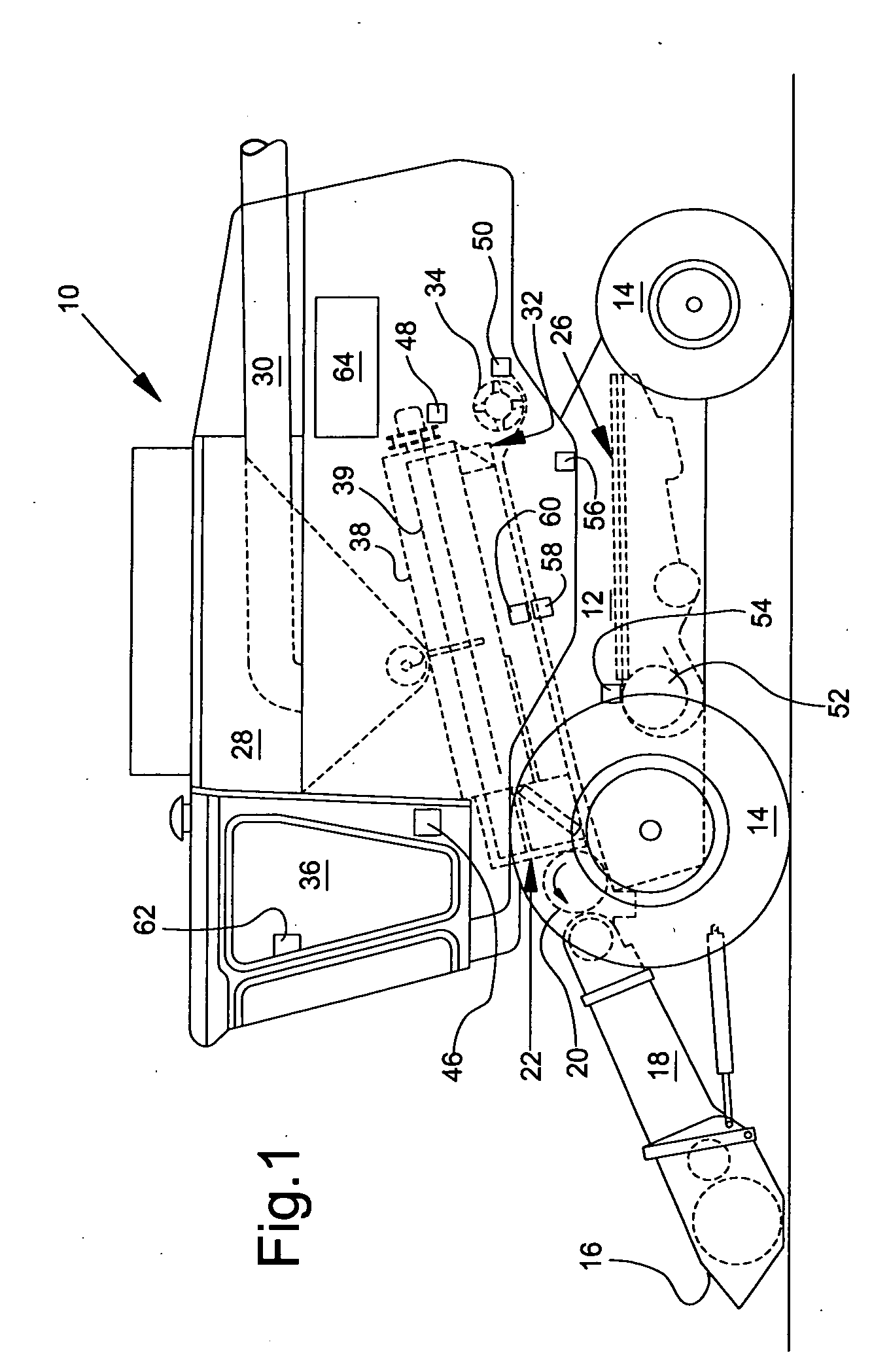
[0020]FIG. 1 shows an agricultural implement 10 in the form of a combine with a chassis 12 and ground wheels 14 extending from this chassis. The invention is explained using this example. A crop harvesting device 16 in the form of a cutting tool is used to receive crops and feed them to a slope conveyor 18. The crops are fed from the slope conveyor 18 to a guide cylinder 20. The guide cylinder 20 guides the crops upwards through an inlet transition region 22 to an axial separating device. The axial separating device comprises a cylindrical rotor housing 38 and a rotor 39 arranged in the rotor housing 38.

[0021] The axial separating device threshes and separates the harvested material. Grain and chaff fall through grates on the floor of the axial separating device into a cleaning system 26. The cleaning system 26 removes the chaff and feeds the clean grain to a (not shown) grain elevator. The grain elevator deposits the clean grain into a grain tank 28. The clean grain in the grain t...


PUM


Abstract

The invention relates to a monitoring device and to a method for monitoring the function of the components of an agricultural implement, with a vibration sensor for providing signal values containing information on mechanical vibrations generated by moving components of the implement, an operating state detecting device for providing a signal containing information on the operating state of components of the implement, and a calculating device for generating state information on the basis of the state of the components of the implement. The calculating device can be operated to divide the signal values of the vibration sensor on the basis of the corresponding signals of the operating state detecting device into different classes, which correspond to different combinations of the operating states of the components in the detection of the signal values, and to compare the signal values divided into classes or data derived from these signal values with comparison values for generating state information.

Description

FIELD OF THE INVENTION [0001] The invention relates to a monitoring device and a method for monitoring the function of the components of an agricultural implement, as well as vibration sensors, detecting devices and calculating devices for generating state information. BACKGROUND OF THE INVENTION [0002] A monitoring device of the type named above is described in DE 101 00 522 A. The implement is equipped with several sensors for detecting vibrations generated by its components during operation. Furthermore, rotational speeds of individual components can be detected. The amplitudes and frequencies of the detected vibrations are allocated by a calculating device on the basis of the measured rotational speeds to individual components of the machine and compared with allocated comparison values. Alternatively, the vibrations are allocated to the components on the basis of their already known rotational speeds. The monitoring device enables recognition of defective components on the basi...

Claims


Application Information

Patent Timeline
Patent Type & Authority Applications(United States)
IPC IPC(8): G06F19/00
CPCA01D41/127G07C5/0808A01D75/18
Inventor BECK, FOLKERBISCHOFF, LUTZ
Owner DEERE & CO
Why Eureka
Try Eureka