Projection system and method

a projection system and projection method technology, applied in the field of projection system and method, can solve the problems of limited leds, and inability to achieve the required output optical power, etc., and achieve the effect of large and clear image and consume a reasonable amount of electric power

Inactive Publication Date: 2006-12-14
EXPLAY
View PDF5 Cites 163 Cited by
  • Summary
  • Abstract
  • Description
  • Claims
  • Application Information

AI Technical Summary

Benefits of technology

[0026] The present invention also provides a solution for a problem associated with the following: It is often the case that to be displayed is alphanumeric and graphical information generated in mobile, battery operated devices. Such display has to create a reasonably large and clear image and consume a reasonably low amount

Problems solved by technology

Due to their low output optical power, LEDs have been limited so far to simple illumination/lighting and communication applications.
However, high optical power LEDs are not the only obstacle keeping LED based micro-projectors from being feasible.
A micro-projection system for mobile devices based on the currently available high power LEDs, cannot reach the required output optical power without r

Method used


Image

  • Projection system and method
  • Projection system and method
  • Projection system and method

Examples


Embodiment Construction

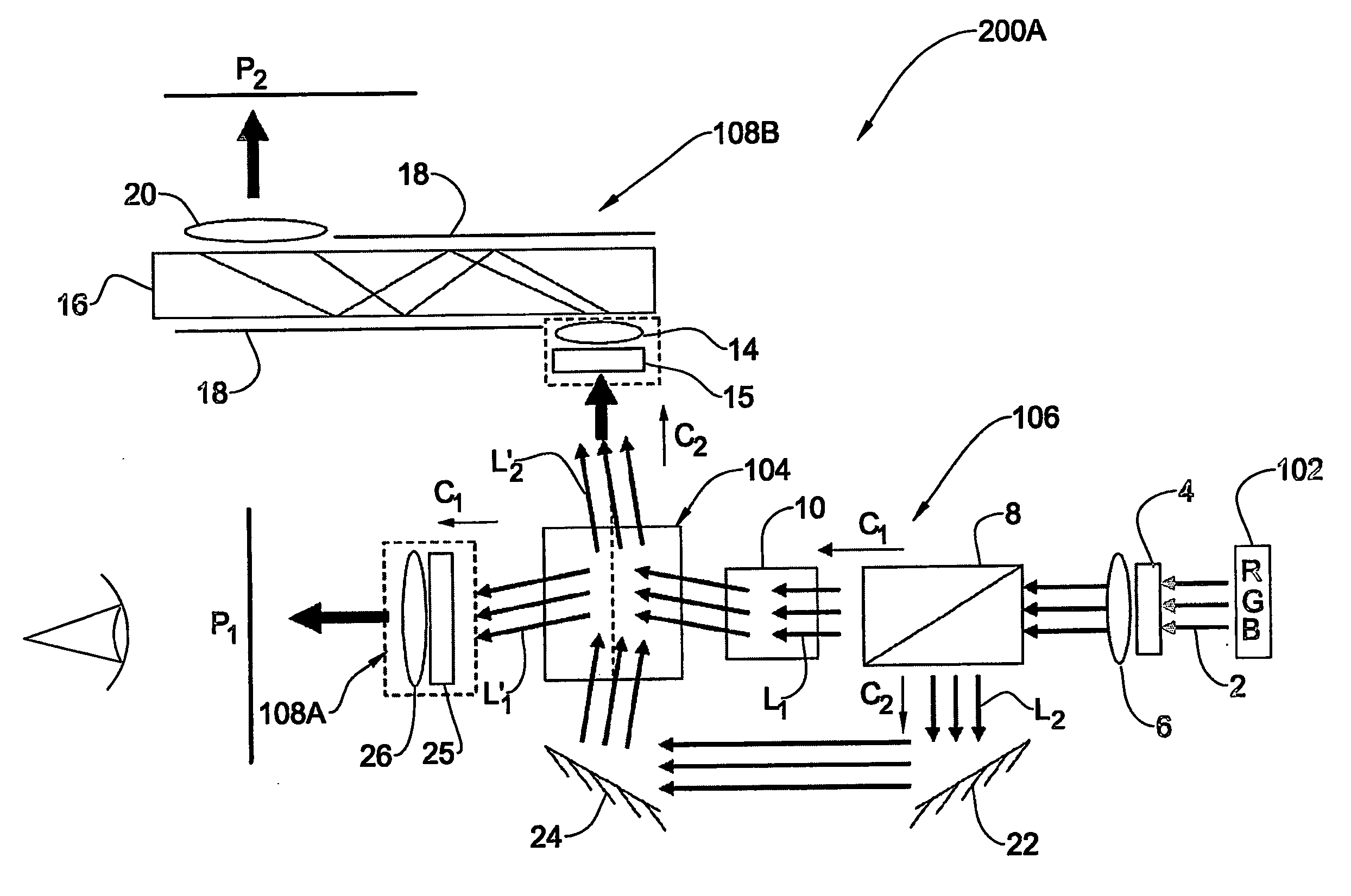
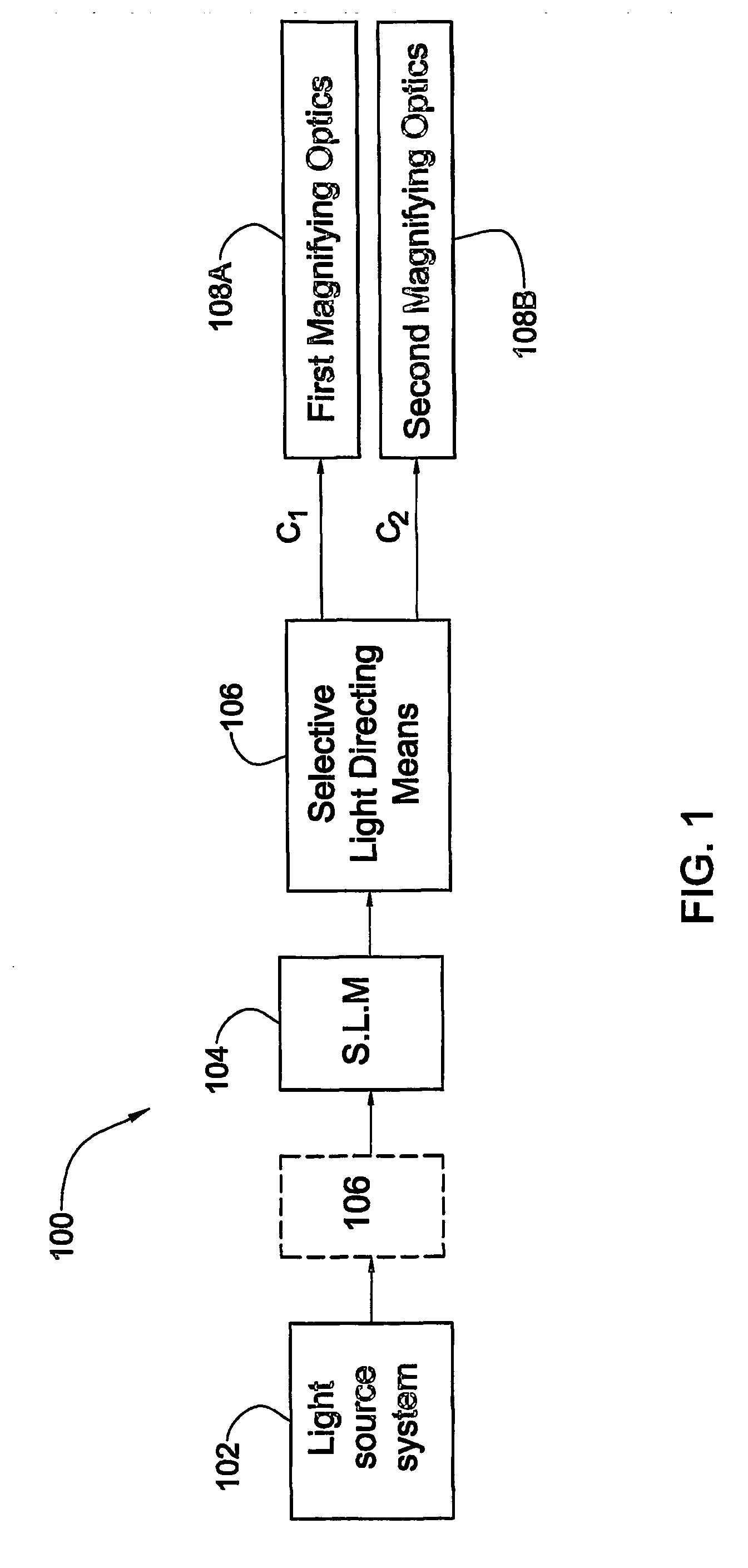
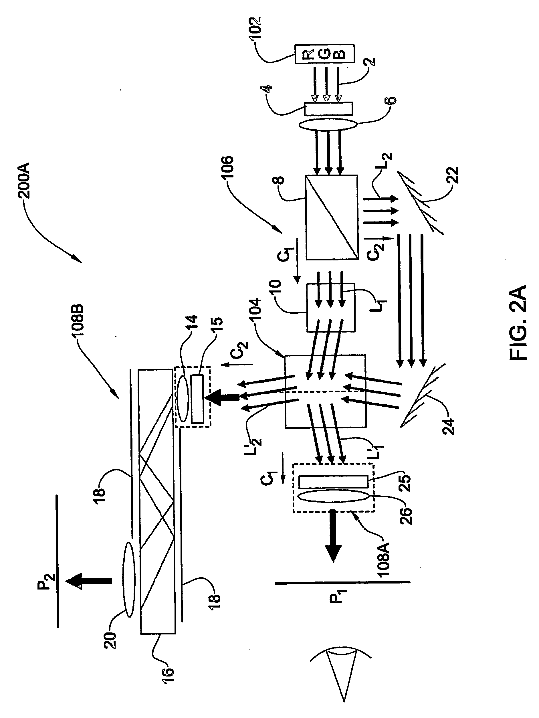
[0055] Referring to FIG. 1, there is schematically illustrated a projection system 100 of the present invention. The system 100 includes a light source system 102; a spatial light modulator (SLM) system 104; a means for selective light directing 106; and first and second magnifying optics 108A and 108B associated with, respectively, first and second projection channels.

[0056] The light source system 102 includes one or more light source assemblies, each with one or more light emitting elements. Preferably, an RGB-source assembly is used. It should be noted, that the light source system preferably includes an optical arrangement operable to provide substantially uniform intensity distribution within the cross-section of the emitted light beam. This optical arrangement includes a diffractive element, commonly referred to as “top-hat”. The light source assembly is preferably of a kind producing a highly polarized light beam.

[0057] The SLM system 104 may be configured to operate in li...


PUM


Abstract

An image projection system and method are presented to project an image on at least one of first and second projection planes. The system comprises a light source system including one or more light source assemblies operable to generate light of one or more predetermined wavelength range; a spatial light modulator (SLM) system including one or more SLM units operable to spatially modulate input light in accordance with an image to be directly projected or viewed; and two optical assemblies associated with two spatially separated light propagation channels, respectively, to direct light to, respectively, the first and second projection planes with desired image magnification. The system is configured to selectively direct the input light propagating towards the SLM system or light modulated by the SLM system to propagate along at least one of the two channels associated with the first and second projection planes, respectively.

Description

FIELD OF THE INVENTION [0001] This invention relates to a projection system and method. BACKGROUND OF THE INVENTION [0002] The entertainment market evolved enormously during the past several years, with the introduction of “front projection”, “rear projection” systems and near eye (direct view) systems. In a front projection system, an observer faces a front projection screen on the same side as the side on which image rays are projected, and sees the displayed picture. In a rear projection system, an observer sees a displayed picture on the side opposite to the side onto which image rays are projected. In a near eye system, the viewer views an enlarged virtual image of an SLM itself as the display (therefore called direct view) [0003] U.S. Pat. No. 6,485,146 discloses a low-profile integrated front projection system configured to coordinate specialized projection optics and an integral screen optimized to work in conjunction with the optics to create the best viewing performance an...

Claims


Application Information

Patent Timeline
IPC IPC(8): H04N9/31G03B21/00G03B21/14G03B21/26H04NH04N5/74H04N17/00
CPCH04N5/7416H04N9/3108H04N9/3114H04N9/3197H04N9/3141H04N9/3147H04N9/3129H04N5/74G03B21/26G03B21/14G03B21/00
Inventor KAPELLNER, YUVALMANOR, GOLANZALEVSKY, ZEEVEYAL, IZHARCOHEN, NADAVOLEISKI, DANIEL
Owner EXPLAY
Why Eureka
Try Eureka