

Optical element, retardation plate using same, optical laminated body,and display apparatus
- Summary
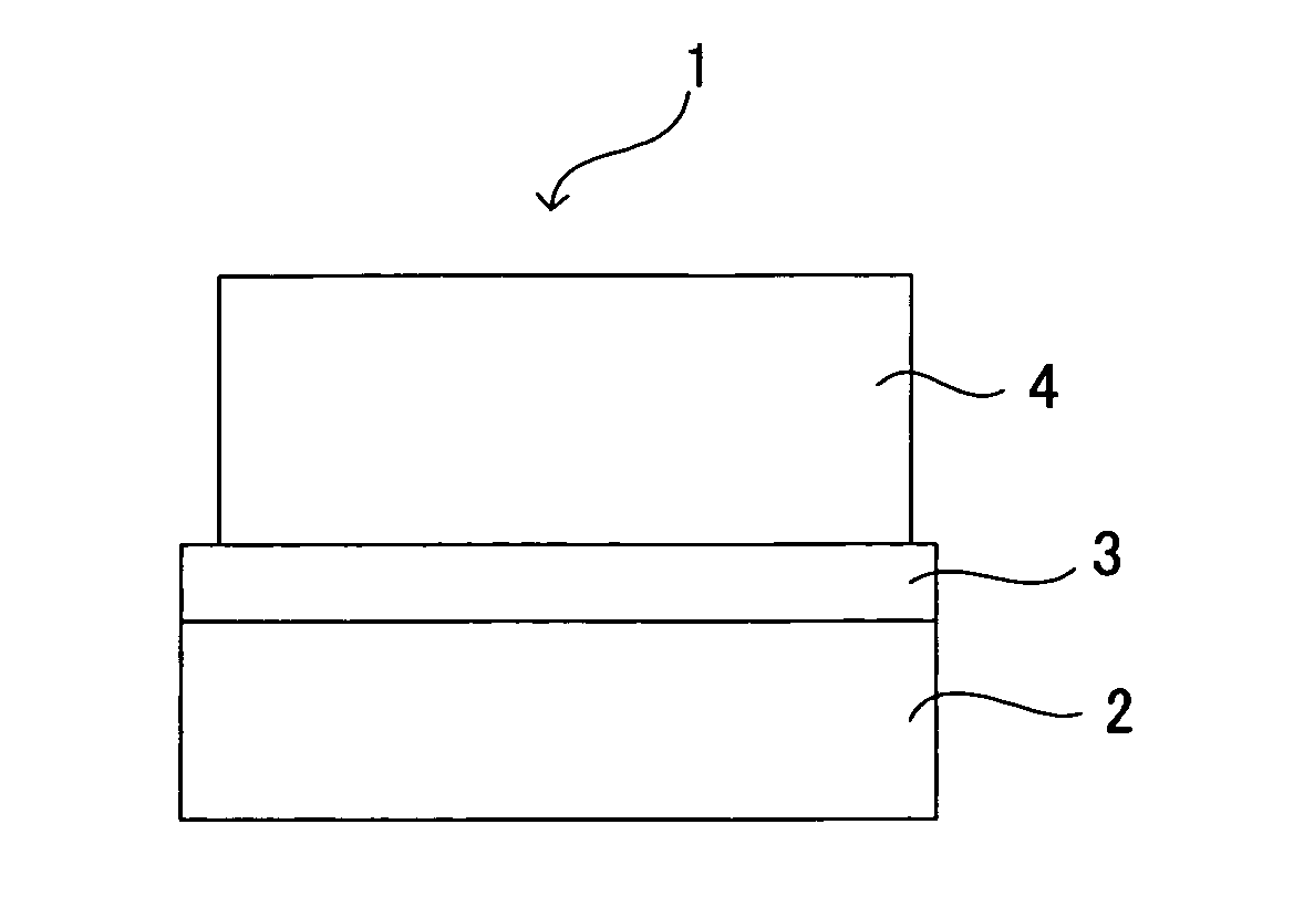
- Abstract
- Description
- Claims
- Application Information
AI Technical Summary
Benefits of technology
Problems solved by technology
Method used
Image

Examples
example 1
Formation of the Hard Coating Layer
[0077] A coating solution of 40% by weight solid content concentration was prepared by dissolving 40 g of Kayarad PET-30 (produced by NIPPON KAYAKU CO., LTD.) and 2 g of IRGACURE 907 (produced by Ciba Specialty Chemicals) in 60 g of a methyl ethyl ketone.
[0078] The coating solution was coated onto a triacetyl cellulose film TD-80 (produced by Fuji Photo Film Co., Ltd.) by the bar coating method so as to have the film thickness after drying of 4 μm, and a heat drying operation was carried out for 3 minutes at 90° C. Then, under the nitrogen atmosphere, an ultraviolet ray curing process comprising the step of exposing a light beam of a high pressure mercury lamp by 100 mj / cm2 was carried out so as to form a hard coating layer.
Formation of the Alignment Layer
[0079] An alignment layer solution of a 1% by weight solid content concentration was prepared by dissolving 99 g of a cyclohexanone in 1.0 g of a photo alignment film material containing a p...
example 2
Formation of the Hard Coating Layer
[0085] A coating solution of 40% by weight solid content concentration was prepared by dissolving 40 g of Kayarad PET-30 (produced by NIPPON KAYAKU CO., LTD.) and 2 g of IRGACURE 907 (produced by Ciba Specialty Chemicals) in 60 g of a methyl ethyl ketone.
[0086] The coating solution was coated onto a triacetyl cellulose film TD-80 (produced by Fuji Photo Film Co., Ltd.) by the bar coating method so as to have the film thickness after drying of 4 μm, and a heat drying operation was carried out for 3 minutes at 90° C. Then, under the nitrogen atmosphere, an ultraviolet ray curing process comprising the step of exposing a light beam of a high pressure mercury lamp by 100 mj / cm2 was carried out so as to form a hard coating layer.
Formation of the Alignment Layer
[0087] An alignment layer solution of a 1% by weight solid content concentration was prepared by dissolving 99 g of a cyclohexanone in 1.0 g of a photo alignment film material containing a p...
example 3
[0093] It was carried out in the same manner as in the example 1 except that 0.05 g of a 3-glycydoxy propyl triethoxy silane (KBE 403 produced by Shin-Etsu Chemical Co., Ltd.) having an epoxy group at the end was added as the silane compound in the liquid crystal layer forming coating solution of the example 1.
PUM
 Abstract
Description
Claims
Application Information