System, including method and apparatus for percutaneous endovascular treatment of functional mitral valve insufficiency

a technology of mitral valve and endovascular treatment, which is applied in the field of percutaneous treatment of heart valve disease, can solve the problems of incompetence of the valve and impunity, and achieve the effect of avoiding occluded and occluded patients

Inactive Publication Date: 2006-12-14
THE INT HEART INST OF MONTANA FOUND
View PDF20 Cites 26 Cited by
  • Summary
  • Abstract
  • Description
  • Claims
  • Application Information

AI Technical Summary

Benefits of technology

[0022] The system of the present invention involves several endovascular apparatus or devices designed to be deployed within the anterior and posterior interventricular veins or only in the posterior interventricular vein. The delivery or deployment system follows the general principles well established in interventional cardiology. A percutaneous or small incision provides access to a peripheral vein (usually the femoral) and a single or double steerable guide wires are inserted through the coronary sinus opening, into the posterior or into both the posterior and anterior interventricular veins until their tips are placed close to the left ventricular apex. A single delivery catheter is then inserted following the guide wire until it is placed in the posterior interventricular vein parallel to the posterior papillary muscle. Alternatively a second guide wire is placed in the anterior interventricular vein. Guidance of the catheter / s is done under fluoroscopic control and transthoracic or transesophageal echocardiography used simultaneously to determine the degree of mitral regurgitation and location and changes in the position of the posterior papillary muscle. The delivery catheter(s) can carry a balloon, or a balloon expanding stent or a self expanding stent of a size corresponding to the size of the patient and degree of mitral regurgitation. A stiff rod, wire or plate can be incorporated into the balloon or stent to stabilize it (them) within the interventricular vein(s). A retaining endovascular plate can be also incorporated in order to limit the outward dilatation of the balloon while promoting its dilatation towards the left ventricular wall and therefore pushing medially the papillary muscle. The stent and retaining plate may be combined into another device so long as the device causes permanent medial displacement of the papillary muscle(s). Alternatively, the delivery catheter can have two small balloons placed at the apical and proximal parts of the delivery catheter so that when inflated they occlude the vein proximal and distal to the balloon or stent. Occlusion of the vein between these two points will result in clotting of the blood within these two points. This system will prevent bleeding if laceration of the vein occurs due to balloon over-dilatation. Also, the delivery catheter can have ports to administer drugs that induce blood clotting or substances that polymerize when in contact with blood between the occluding balloons.
[0024] In another aspect of the present invention, guide wires are placed in both the posterior and anterior interventricular veins. Small magnets are threaded through the guide wires until both veins are filled with the magnets. Their mutual attraction will bring closer both papillary muscles. Also, a similar result can be achieved by delivering through both guide wires pre- shaped, memory rods that are bound together at the level of the coronary sinus. Once the delivery catheters are removed, an inverted “U” shape device results that brings the two interventricular veins closer to one another and consequently also the papillary muscles.

Problems solved by technology

This displacement pulls on the chordae tendinae of the mitral valve that tether down the anterior and posterior leaflets which cannot come in contact and therefore the valve becomes incompetent.
Also that these veins are not essential for the venous drainage of the heart and therefore can be occluded with impunity.

Method used


Image

  • System, including method and apparatus for percutaneous endovascular treatment of functional mitral valve insufficiency
  • System, including method and apparatus for percutaneous endovascular treatment of functional mitral valve insufficiency
  • System, including method and apparatus for percutaneous endovascular treatment of functional mitral valve insufficiency

Examples


Embodiment Construction

[0042] The following specification, taken in conjunction with the drawings, sets forth the preferred embodiments of the present invention. The embodiments of the invention disclosed herein are the best modes contemplated by the inventors for carrying out their invention in a commercial environment, although it should be understood that various modifications can be accomplished within the parameters of the present invention.

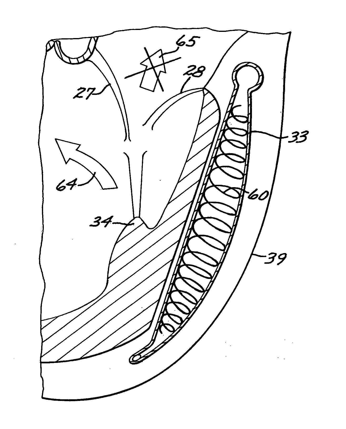
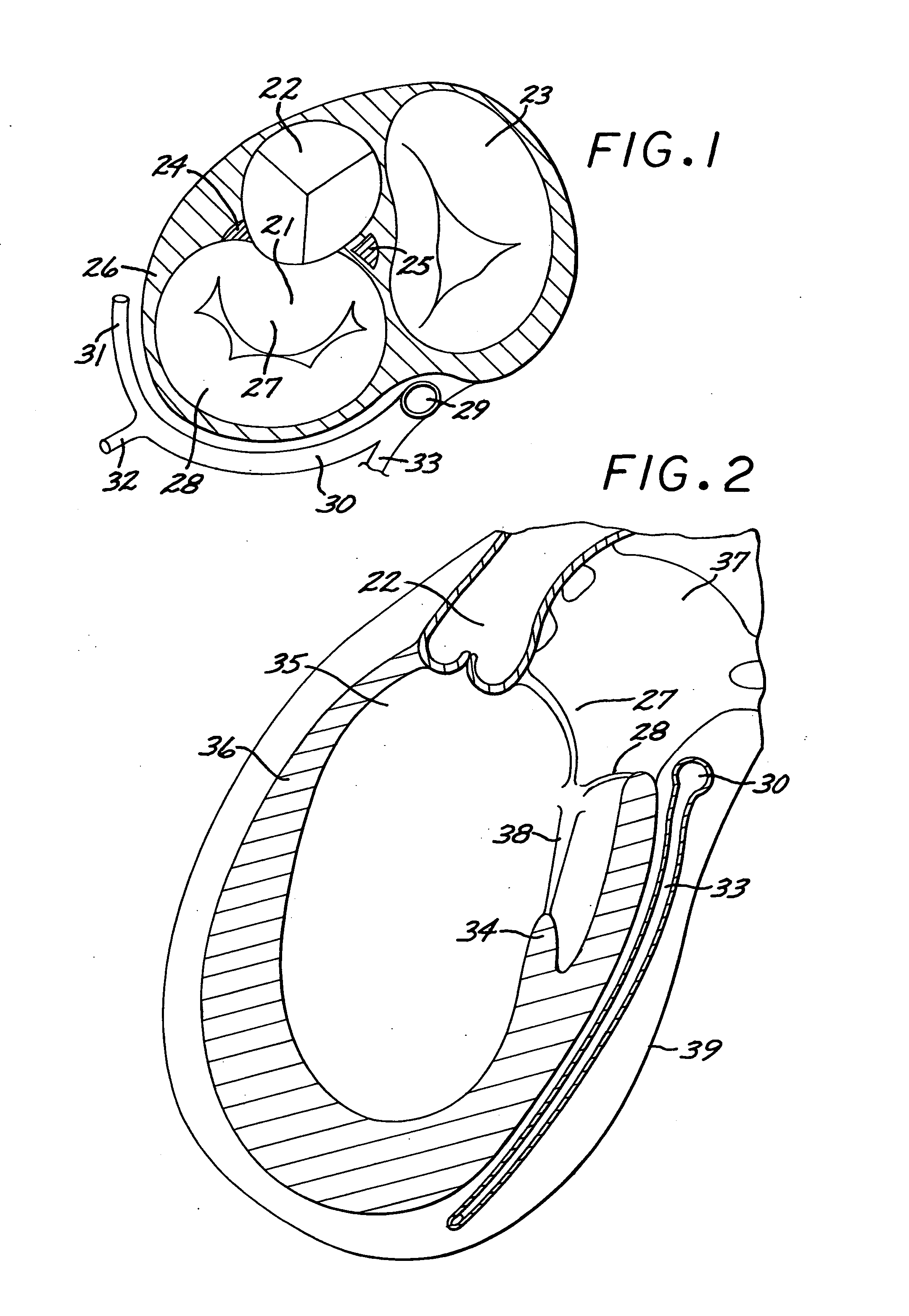
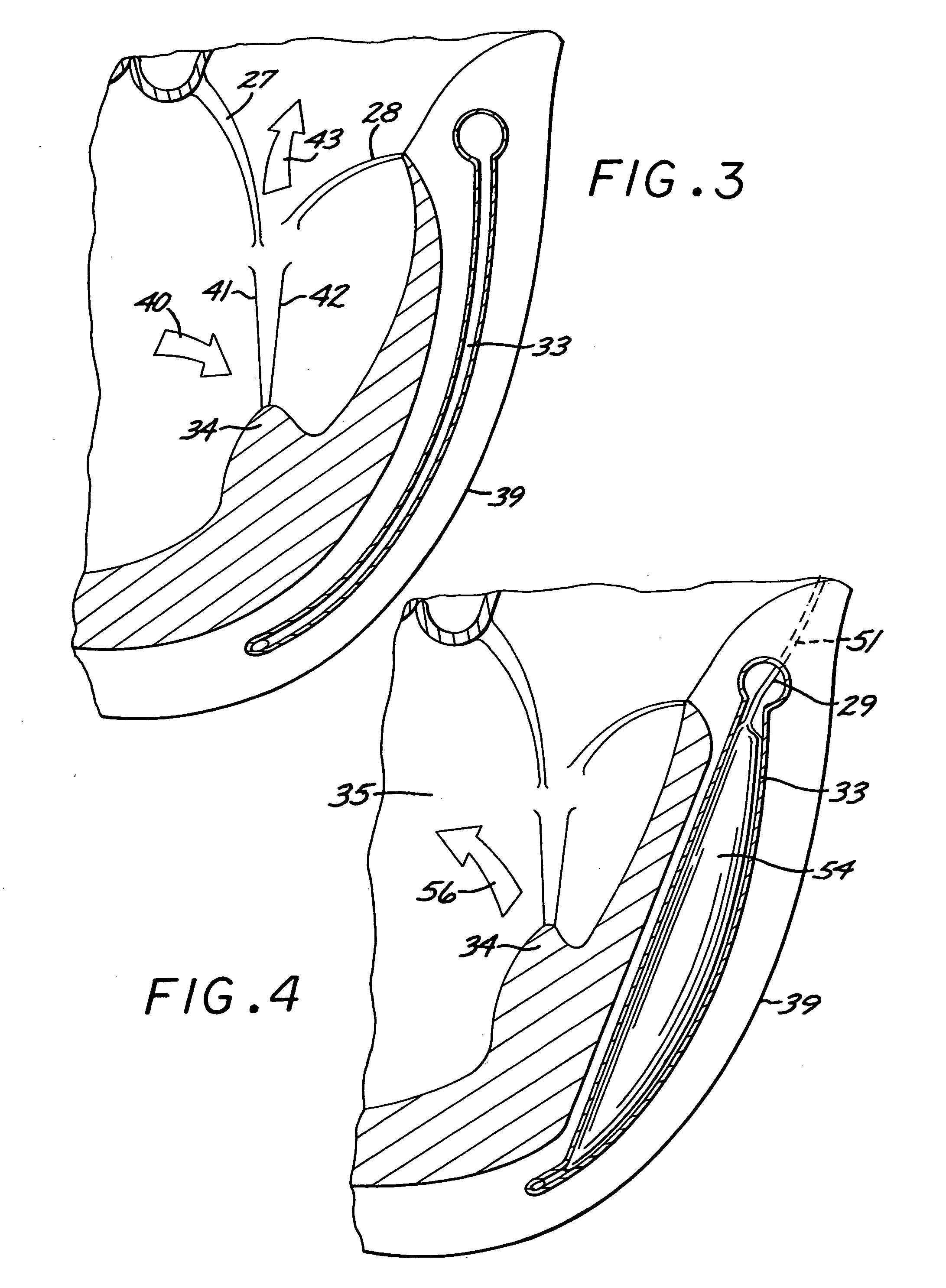
[0043] Referring now to the drawing figures, FIG. 1 is a sketch of the base of the heart which is essential for the understanding of the present invention. The mitral valve 21, aortic valve 22 and tricuspid valve 23 are shown with the left 24 and right 25 fibrous trigones of the heart supporting the mitral annulus 26 together with the anterior 27 and posterior 28 leaflets of the mitral valve 21. The coronary sinus opening into the right atrium 29 and the coronary sinus 30 with its branches are shown: the anterior interventricular vein 31, the marginal vein 32 and...


PUM


Abstract

Among the four heart valves, the mitral is the most frequently affected by disease resulting in defective valve opening (stenosis) or incomplete closure (insufficiency). Most often this is due to distortion of the valve apparatus secondary to rheumatic or degenerative disease. These lesions, called “organic” require open heart surgery. In patients with coronary disease or with dilated cardiomyopathy the mitral valve can be insufficient although structurally normal. These valves are “functionally” insufficient. Because of the poor condition of these patients where open heart surgery carries a significant operative risk, less invasive percutaneous alternatives are being explored today. The present novel invention represents a radical departure from other procedures because it repositions the posterior papillary muscle utilizing a device located in the interventricular veins.

Description

CLAIM OF PRIORITY OF PROVISIONAL APPLICATION [0001] The present application claims the priority of provisional application Ser. No. 60 / 688,319, filed on Jun. 7, 2005.BACKGROUND OF THE INVENTION [0002] 1. Field of the Invention [0003] The present invention is in the novel field of percutaneous treatment of heart valve disease and in particular of the so called “functional” mitral valve insufficiency. [0004] More specifically, the present invention relates to apparatus and methods for treating mitral valve insufficiency in cases where the mitral valve, although structurally intact, leaks because of changes in its geometry. These so-called “functional” mitral regurgitations are typically present in patients with coronary (ischemic) disease or with dilated cardiomyopathy. The present invention is a completely original departure from the prior art involving the restoration of the mitral valve papillary muscle geometry through the percutaneous placement of a device in the posterior, anter...

Claims


Application Information

Patent Timeline
Patent Type & Authority Applications(United States)
IPC IPC(8): A61F2/06A61M29/02A61F2/94
CPCA61B2017/00243A61F2210/009A61F2/2451
Inventor DURAN, CARLOS M.G.SANZ, MARK L.MARTINEZ DE UBAGO, JOSE LUISDE UBAGO, YON PATRIK MARTINEZ
Owner THE INT HEART INST OF MONTANA FOUND
Why Eureka
Try Eureka