
Valve annulus reduction system

a valve annulus and valve technology, applied in the field of medical devices, can solve the problems of complex procedures, insufficiency of valves, and cardiac dysfunction, and achieve the effects of reducing the risk of cardiac failur

Inactive Publication Date: 2006-12-14
MEDTRONIC VASCULAR INC
View PDF23 Cites 505 Cited by
  • Summary
  • Abstract
  • Description
  • Claims
  • Application Information

AI Technical Summary

Benefits of technology

[0017] The invention further provides a method for treating a dilated heart valve comprising delivering a tension device comprising a barbed anchor connected to a radiused anchor with a cord to a location within an atrium proximal the dilated heart valve. The method furthe...

Problems solved by technology

Valve insufficiency is a potentially grave health issue that can lead to cardiac dysfunction.
These procedures are complex, time consuming, and involve many risks attendant with open cardiac surgery.
Complications may occur, and recovery time may be significant.
The placement of knotted sutures by catheter can be very difficult and time consuming.
Artificial heart valves for temporary use are known in the art, but present certain problems.
Some designs are complex, requiring inflating and deflating balloons to alternately block and permit flow.
Such designs require complex sensing and control systems.
Other designs fail to provide access for tools that must reach the valve site for removal of the native valve and placement of the prosthetic valve.
The prior art solutions incur potentially undesirable trauma to the cardiac tissue.

Method used


Image

  • Valve annulus reduction system
  • Valve annulus reduction system
  • Valve annulus reduction system

Examples


Embodiment Construction

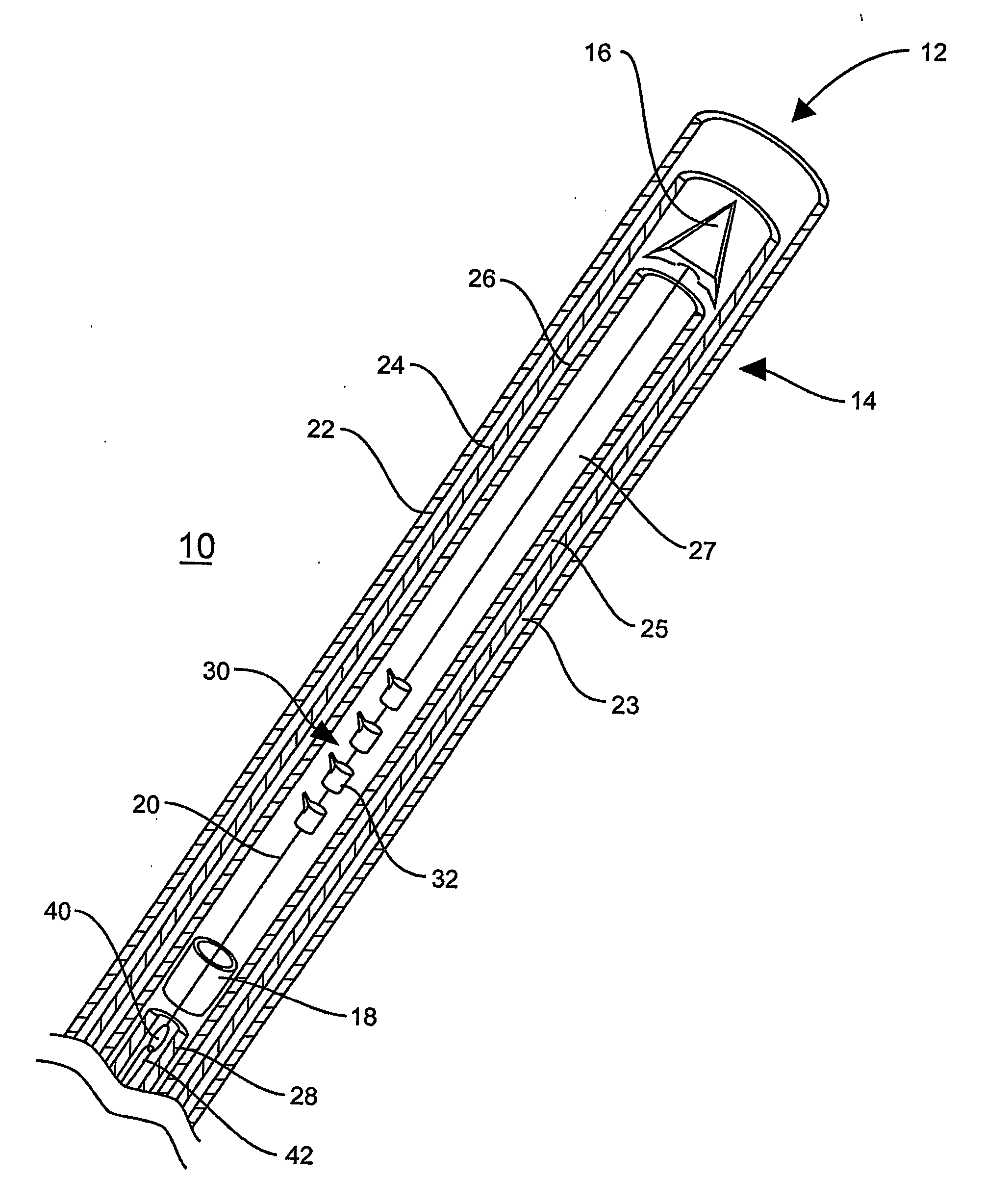
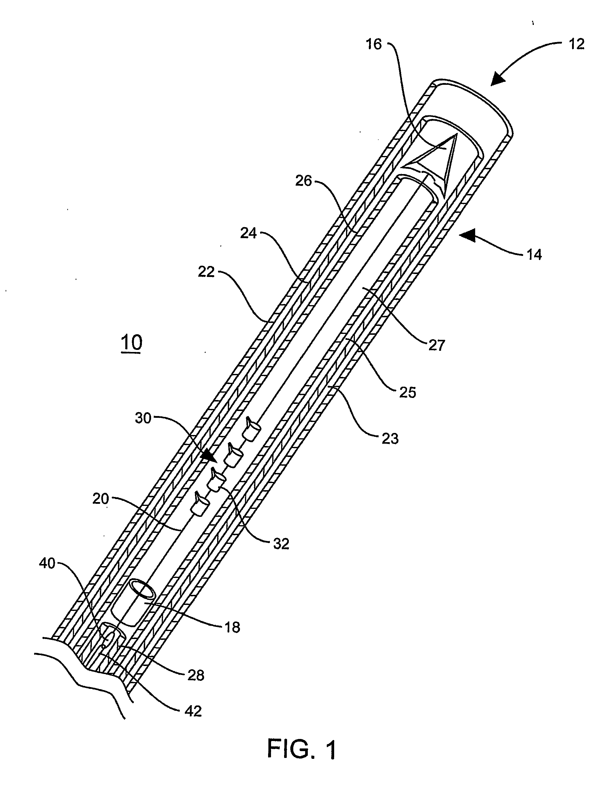
[0027] One aspect of the present invention is a system for treating a dilated heart valve. The system may be used to treat any one of the cardiac valves. The description below provides detail for treating the mitral valve via a catheter routed through the coronary sinus. Alternative embodiments may treat mitral or tricuspid valves using a tension device delivered via a catheter through a coronary vein or artery and into a chamber of a heart. The coronary vessels used for accessing a heart chamber may lie in either a septal wall or an outer, free wall of the heart. The heart chamber may be an atrium or a ventricle. The tension device is routed from the coronary vessel into the adjacent chamber of the heart. A distal anchor of the tension device is embedded in an opposing chamber wall and a proximal anchor of the tension device is deployed in the coronary vessel. Applying tension to the tension device will shorten the length thereof, thus reducing the dilated annulus of an adjacent ca...


PUM


Abstract

System (10) for treating a dilated heart valve includes a dilivery device. Tension device (12) is slidably received within the lumen of delivery device (14) for delivery to and deployment at the treatment area. Delivery device (14) includes a plurality of arranged catheters including an inner catheter (26) within the lumen of an outer catheter (22). Tension device (12) includes a first anchor (16) attached to a second anchor (18).

Description

RELATED APPLICATION [0001] This application claims priority to U.S. Provisional Application No. 60 / 480,201, “Coronary Sinus Approach for Repair of Mitral Valve Insufficiency” to Rany Huynh, et al., filed Jun. 20, 2003, the entirety of which is incorporated by reference.TECHNICAL FIELD [0002] The technical field of this disclosure is medical devices, particularly, for reducing a valve annulus. BACKGROUND OF THE INVENTION [0003] Valve insufficiency is a potentially grave health issue that can lead to cardiac dysfunction. Mitral valve insufficiency may comprise a valve that does not completely shut and affect the seal between the left ventricle and the left atrium. Historically, such a condition necessitated surgical intervention. [0004] Surgical repair of mitral valve insufficiency involved the use of a sternotomy or a similar invasive procedure. After performing a sternotomy, the patients heart would be stopped while the surgeon transected the chambers of the heart to gain access to ...

Claims


Application Information

Patent Timeline
IPC IPC(8): A61F2/24A61BA61B17/00A61B17/04A61B17/06A61F2/915A61M25/10
CPCA61B17/00234A61B17/0401A61B17/0487A61B2017/00243A61B2017/00783A61B2017/0417A61F2/2481A61B2017/0461A61B2017/0464A61B2017/0496A61B2017/06052A61B2017/06176A61F2/2451A61B2017/0451
Inventor HUYNH, RANYBLOOM, ELIOTLEMMON, JACKRYAN, TIMOTHY R.
Owner MEDTRONIC VASCULAR INC
Features
  • Generate Ideas
  • Intellectual Property
  • Life Sciences
  • Materials
  • Tech Scout
  • Unparalleled Data Quality
  • Higher Quality Content
  • 60% Fewer Hallucinations
Learn More