Method for monitoring film thickness using heterodyne reflectometry and grating interferometry

Inactive Publication Date: 2006-12-21
VERITY INSTR
View PDF8 Cites 19 Cited by
  • Summary
  • Abstract
  • Description
  • Claims
  • Application Information

AI Technical Summary

Benefits of technology

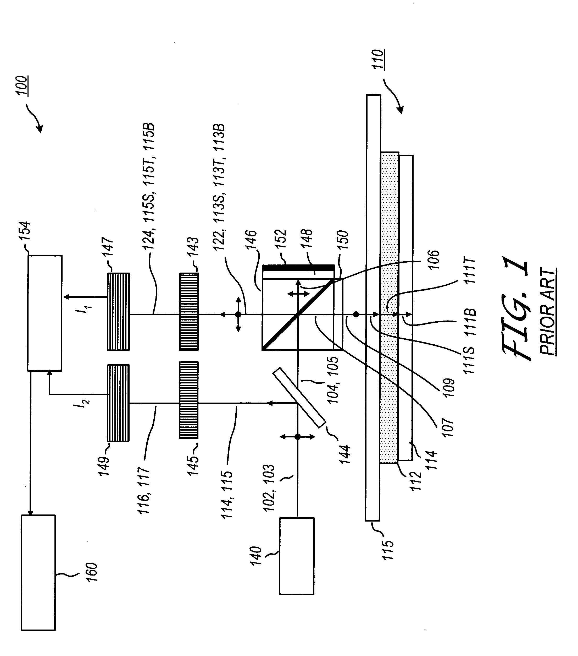
[0019] The reflected beam may be optimized for film thickness measurement by setting the system incidence angle near the Brewster's angle for the film, which is controlled by its refractive index at the source wavelength. The greatest phase shift between reference signal and measurement signal exists where the incidence of the beam is set to Brewster's angle. The measurem

Problems solved by technology

Thus, the accuracy of the results is adversely affected by surface roughness.
Another limitation of the prior art common axis method is that it does not measure or calculate an actual thickness parameter for a film layer.
The principle drawback of these types of devices is that since the heterodyning is achieved by frequency modulating the source and thinnest film measurable is limited by its bandwidth.
However, separating the reference bea

Method used


Image

  • Method for monitoring film thickness using heterodyne reflectometry and grating interferometry
  • Method for monitoring film thickness using heterodyne reflectometry and grating interferometry
  • Method for monitoring film thickness using heterodyne reflectometry and grating interferometry

Examples


Embodiment Construction

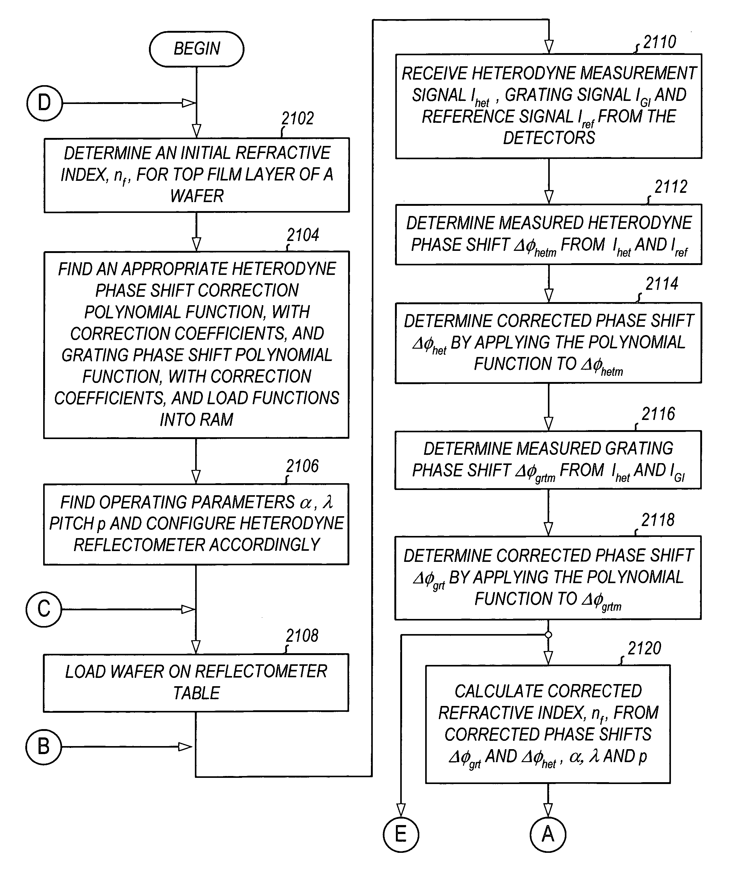
[0055] This present invention is useful in monitoring deposition of ultra thin films that are part of semiconductor fabrication. Hence, it can be integrated with deposition tools and diffusion furnaces. Furthermore, the present invention provides an uncomplicated and effective means for extending the use of visible light reflectometry to measure thin-films in the sub 10 Å to 2000 Å film thickness range. Using the present invention, it is possible to obtain superior results by using a monochromatic source with large mean time between failure (MTBF) and a very simple detection scheme. Typically, extension of prior art spectral reflectometers into this thickness region require complex deep ultraviolet (DUV) light sources and reflective or catadioptric optics. Additionally, and in contrast with prior art reflectometers, the present invention does not require a priori knowledge of under layers to determine thickness of several Angstroms thick top layer film. Furthermore, the cost of owne...


PUM


Abstract

A linearly polarized light comprised of two linearly polarized components, orthogonal to each other and with split optical frequencies, is directed toward a film. A detector receives the beam prior to incidence on the film layer and generates a reference signal. The reflected beam is diffracted into zeroth- and first-order bands, which are then detected by separate detectors; a measurement signal is generated from the zeroth-order beam and a grating signal from the first-order beam. The zeroth-order beam's measurement signal and reference signal are analyzed by a phase detector for a heterodyne phase shift, and an accurate film thickness calculated from this phase shift by knowing a refractive index for the film. Additionally, the zeroth-order beam measurement signal is analyzed with the grating signal by a phase detector for detecting a grating phase shift induced by the grating. The refractive index for the film can then be calculated directly from grating phase shift and the heterodyne phase shift for the grating pitch, and the beam's wavelength and incidence angle on the film of the measurement apparatus. Using the refractive index and heterodyne phase shift, the film's thickness is determined for the apparatus. Conversely, the thickness of the film can be calculated independent of the refractive index, and without knowing the film's refractive index, directly from the grating phase shift and the heterodyne phase shift for the apparatus.

Description

CROSS REFERENCES TO RELATED APPLICATIONS [0001] The present application is a continuation-in-part of and claims priority from the co-pending U.S. patent application Ser. No. 11 / 066,933 entitled “Heterodyne Reflectomer for Film Thickness Monitoring and Method for Implementing,” filed Feb. 25, 2005 and currently pending. The above identified application is incorporated by reference herein in its entirety.BACKGROUND OF THE INVENTION [0002] The present invention relates to reflectometry. More particularly, the present invention relates to a reflectometer system and method for obtaining thickness information by measuring phase shift in reflected split frequency signals via heterodyne interferometry. Furthermore, the present invention relates to a method and system for using the heterodyned signals from a heterodyne reflectometer for measuring the thicknesses of thin and ultra thin films formed over substrates. Still more particularly, the present invention relates to a heterodyne reflect...

Claims


Application Information

Patent Timeline
IPC IPC(8): G01B9/02G01B11/02
CPCG01B11/0641G01B11/0625G01B2290/30
Inventor AIYER, ARUN ANANTH
Owner VERITY INSTR
Why Eureka
Try Eureka