Method and apparatus for separating particles by dielectrophoresis

a technology of dielectrophoresis and particle separation, which is applied in the field of microfluidic systems, can solve the problems of limited sample processing rate of flow channels using such electrode arrangements, limited electric fields and dep forces, and limitations of conventional microfluidic dep sorting devices, etc., and achieves the effect of easy tuning to trap/separa

Active Publication Date: 2006-12-28
CFD RES CORP
View PDF12 Cites 27 Cited by
  • Summary
  • Abstract
  • Description
  • Claims
  • Application Information

AI Technical Summary

Benefits of technology

[0013] The present invention represents an advance in the art of dielectrophoretic manipulation of particles in a microfluidic environment. Specifically, particles are separated in a separation chamber comprising at least one pair or preferably two opposing pairs of electrodes that generate c-DEP forces, which act on a mixture of particles in a suspending medium. Particles are deflected and/or blocked by DEP forces generated by the combination of two o

Problems solved by technology

One of the limitations of conventional microfluidic DEP sorting devices derives from the arrangement and operation of the electrodes used to generate electric fields and the resulting dielectric forces.
Since the strengths of the electric fields and DEP forces are limited by cross-sectional dimensions, for example the depth of the channel, and the electrode gap, the sample processing

Method used


Image

  • Method and apparatus for separating particles by dielectrophoresis
  • Method and apparatus for separating particles by dielectrophoresis
  • Method and apparatus for separating particles by dielectrophoresis

Examples


examples

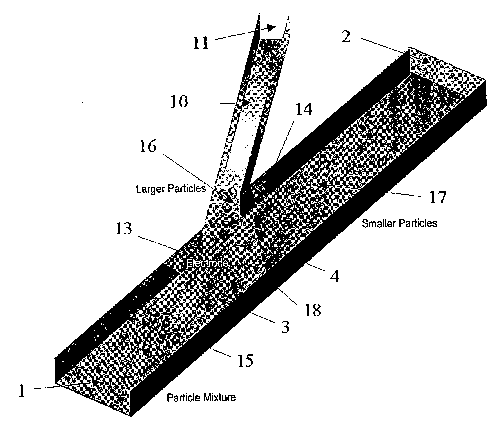
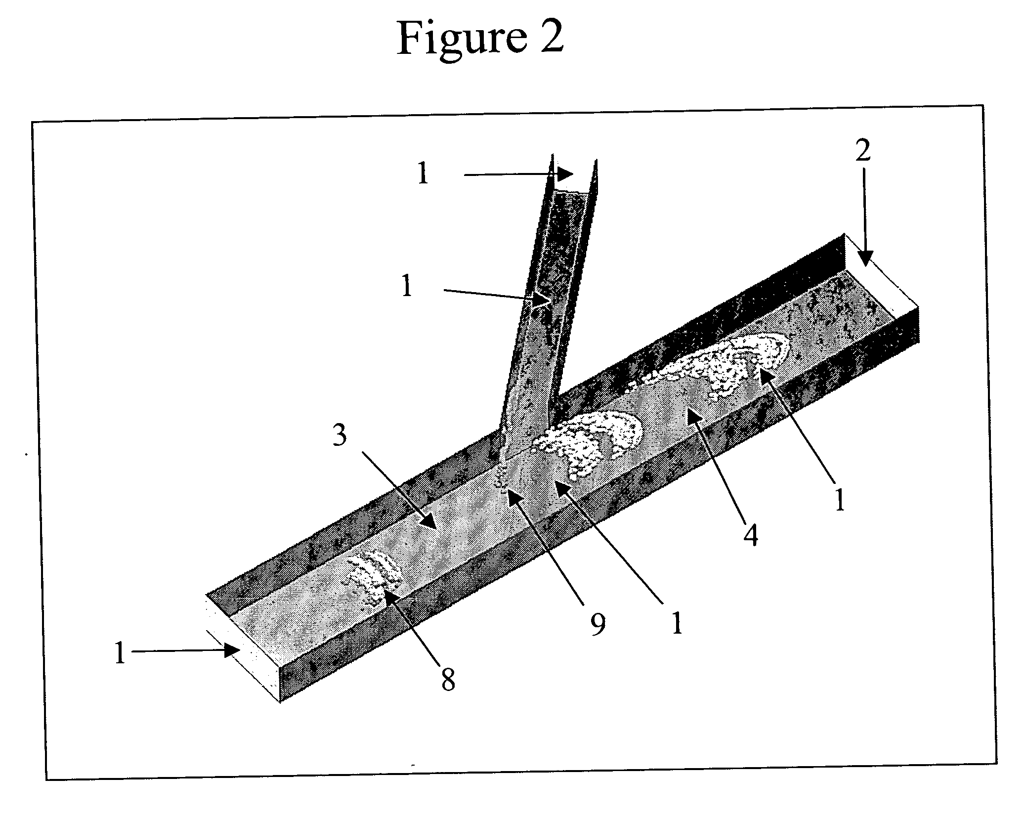
[0049] Separation Chambers: One exemplary separation chamber is illustrated in FIG. 4 and has dimensions of 0.8 mm in width and 0.2 mm in height (normal to the view shown). The inter-electrode gap distance is 0.1 mm for both top and bottom electrode pairs. The side channel forms a 45° angle with the upstream portion of the main flow channel and is 0.2 mm in width and height. Another exemplary separation chamber is shown in FIG. 3, which has the same dimensions as the separation chamber in FIG. 4 but the side channel forms an angle of less than 45° with the downstream portion of the main flow channel.

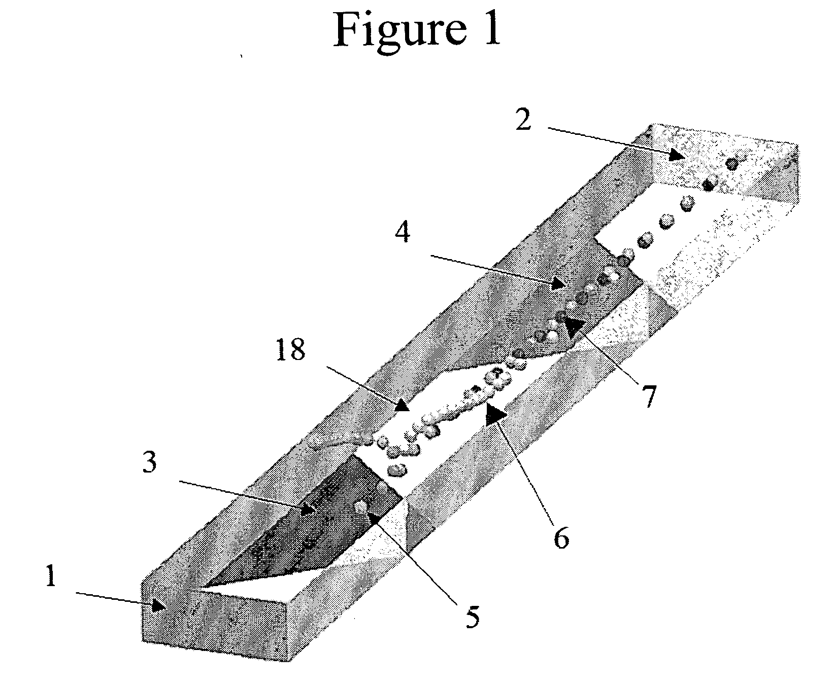
[0050]FIG. 1 illustrates a separation chamber having no side channel and an electrically coupled pair of electrodes in the bottom surface of the flow channel. The gap between electrodes is non-uniform because the shape of the gap is a trapezoid. The separation chamber in this case 50 μm wide and 20 μm deep.

[0051] The length of any separation chamber will depend upon the number of elect...

experimental examples

[0055] A separation chamber having the same dimensions and components as described for the preceding simulation was fabricated and tested. Polystyrene beads having diameters of 1 μm and 9 μm were suspended in water and 1% BSA. Inositol was added until the density of the aqueous solution was equal to the density of the polystyrene beads. The particle suspension was introduced into the inlet of the separation chamber having a flow rate of 2.4 μL / min. The 9 μm beads were diverted into the side channel by applying an AC signal of 10 Mhz frequency and 20 V (p-p) with 180° phase shift to the electrode pairs.

[0056]FIG. 8 shows a prototype separation chamber in use, focusing on the region around the electrodes 3 and 4 and the side channel 10. The dimensions of the separation chamber are the same as those in FIG. 4. The bottom electrode pair 3 and 4 is visible and eclipses the opposing top electrode pair. The inter-electrode gap 18 between the top pair of electrodes 3 and 4 is visible. Blac...


PUM

PropertyMeasurementUnit
Angleaaaaaaaaaa
Angleaaaaaaaaaa
Distanceaaaaaaaaaa

Abstract

Methods and apparatus for the micro-scale, dielectrophoretic separation of particles are provided. Fluid suspensions of particles are sorted and separated by dielectrophoretic separation chambers that have at least two consecutive, electrically coupled planar electrodes separated by a gap in a fluid flow channel. The gap distance as well as applied potential can be used to control the dielectrophoretic forces generated. Using consecutive, electrically coupled electrodes rather than electrically coupled opposing electrodes facilitates higher flow volumes and rates. The methods and apparatus can be used, for example, to sort living, damaged, diseased, and/or dead cells and functionalized or ligand-bound polymer beads for subsequent identification and/or analysis.

Description

STATEMENT REGARDING FEDERALLY SPONSORED RESEARCH OR DEVELOPMENT [0001] Statement of Government Rights [0002] The U.S. Government may have certain rights in this invention pursuant to SBIR Contract Numbers M67854-03-C-5015 and M67854-04-C-5020 awarded by the Marine Corps Systems Command.CROSS-REFERENCE TO RELATED APPLICATIONS [0003] Not Applicable INCORPRATED-BY-REFERENCE OF METARIAL SUBMITTED ON A COMPACT DISC [0004] Not Applicable BACKGROUND OF THE INVENTION [0005] 1. Field of the Invention [0006] This invention relates to microfluidic systems for handling or processing fluid suspensions of dielectric particles including living cells, spores, viruses, polymer beads, and aggregates of macromolecules. In particular, the invention involves the use of dielectrophoresis (DEP) induced forces to manipulate or control the velocity, including direction, of dielectric particles in microfluidic devices. The invention can be employed in a wide variety of applications including, but not limited...

Claims


Application Information

Patent Timeline
IPC IPC(8): B41J2/05
CPCB03C5/026B03C5/005
Inventor FENG, JIANJUNWANG, GUIRENKRISHNAMOORTHY, SIVARAMAKRISHNANPANT, KAPILSUNDARAM, SHIVSHANKAR
Owner CFD RES CORP
Why Eureka
Try Eureka