Process for corrosion control in boilers

a technology of corrosion control and boiler, which is applied in the direction of instruments, combustion types, and the nature of treatment water, etc., can solve the problems of insufficient cost-effectiveness of replacement alloys, the inability to replace superheater pendants, and the corrosion of high temperature surfaces of chloride-induced high temperature surfaces in waste to energy boilers. the effect of operating load

Inactive Publication Date: 2006-12-28
FUEL TECH
View PDF10 Cites 8 Cited by
  • Summary
  • Abstract
  • Description
  • Claims
  • Application Information

AI Technical Summary

Benefits of technology

[0022] It is an object of the invention to provide a method for controlling corrosion of the high temperature surfaces of a boiler, particularly a waste to energy boiler under operating load.

Problems solved by technology

Over several recent years the literature has extensively reported that chloride induced corrosion of high temperature surfaces in waste to energy (WTE) boilers is one of the most costly problems in the industry.
This problem can result in replacement of superheater pendants as often as annually in some units or the costly use of higher alloyed materials to either shield the metal surfaces or serve as replacement tube material.
The cost-effectiveness of the replacement alloys has not been proven in many cases, and the industry has been looking for alternative solutions.
In U.S. Pat. No. 6,478,948, Breen, et al., indicate that until recently, furnace boiler tubes corroded slowly and had a service life of 20 to 30 years, but the introduction of low NOx burners has increased the rate of boiler tube corrosion and can reduce their life expectancy to only 1 to 2 years.
Second, they say that if the oxide film is not present, the iron surface is attacked and pitted by condensed phase chlorides which may be present.
While the problems of boiler corrosion are well documented and there is a growing understanding of the causes, the available solutions to these problems are not as easily facilitated or economical as would be desired.
In the case of isolated corrosion, especially on superheater pendant surfaces, which can experience corrosion rates ranging from 0.020 to 0.050 inches per month, tube failures can occur in as little as seven months and create a need for replacement of the entire pendant annually.
It is well known that corrosion by high CO levels and reducing atmospheres occurs in the first pass above the grate in-furnace.
As with Breen, et al, they point out that sulfur compounds can be corrosive compounds under some circumstances and can influence the corrosion by chlorine.
This would result in formation of sulfates and volatile HCl.
However, if the gas reaches the cooler tube walls before the reaction is completed, the alkali metals will tend to condense on the cooler metal.
In this case, further sulfate formation can occur on the metal under the release of HCl, and that causes high chlorine partial pressures and enhanced corrosion.
As a result, formation of FeCl2 can decrease the adherence of the oxide scale or can cause spallation of the oxide layer.
These new oxides are not formed as a perfect layer and do not offer protection.
In this process, the chlorine has a catalytic effect on the oxidation of the metal resulting in enhanced corrosion.
From the above, Rademakers, et al., conclude that low alloy steels and iron-base alloys have limited resistance against active oxidation.
Corrosion of heat transfer surfaces in boilers has been a major problem, particularly WTE units which generate highly corrosive flue gases, and continues to trouble the industry.
There remains a present challenge to provide a process for taking necessary corrective action to address the corrosion boilers, particularly in WTE units, before damage becomes excessive and requires expensive shut down and repair.

Method used


Image

  • Process for corrosion control in boilers
  • Process for corrosion control in boilers
  • Process for corrosion control in boilers

Examples


Embodiment Construction

[0040] The invention provides processes for monitoring corrosion and for controlling corrosion, which are described below with reference to exemplary embodiments. Because the monitor and the processes are especially useful in the control of chloride corrosion in waste to energy boilers, they will be described in this context while those skilled in the art will see the application of the invention to other environments.

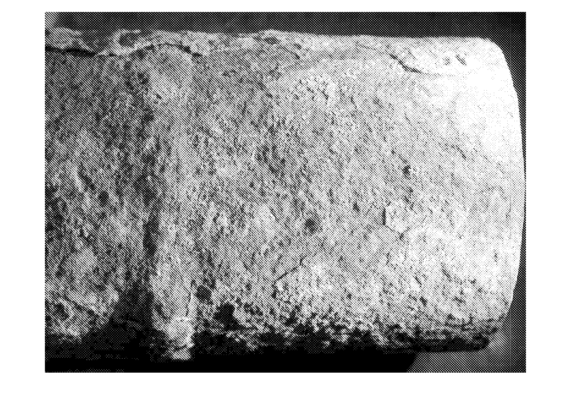
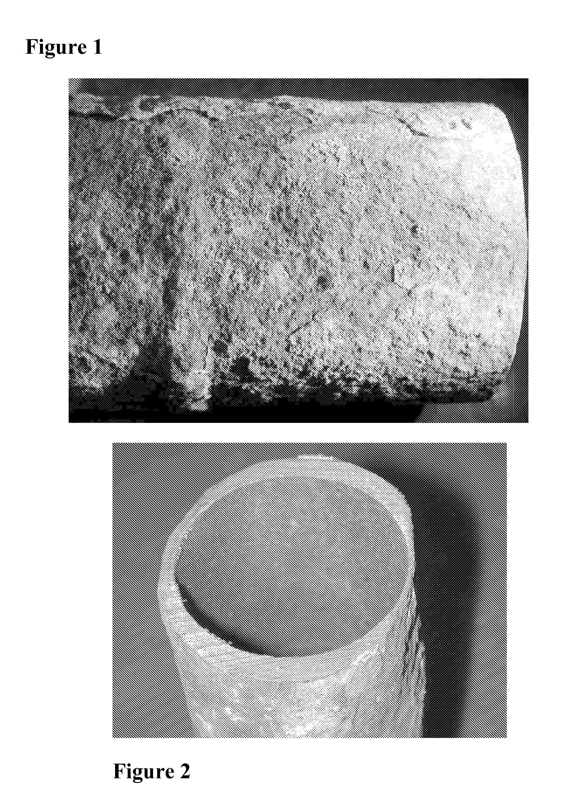
[0041] As discussed above, the problem of high temperature corrosion within waste to energy boilers by chlorides is one of the most costly in the industry. The invention enables assessment and control of corrosion of high temperature surfaces and preferably involves the controlled introduction of treatment chemicals by targeted in furnace injection to reduce corrosion while maximizing combustion efficiency. To illustrate the problem of chloride caused corrosion, applicants provide FIG. 1, which is a photograph showing a close-up of rough, wasted surface of a superheat...


PUM

PropertyMeasurementUnit
corrosion ratesaaaaaaaaaa
temperaturesaaaaaaaaaa

Abstract

A corrosion control process is described. The process is especially useful in the control of chloride corrosion in waste to energy boilers. Corrosion of high temperature surfaces can be assessed by the monitor and controlled introduction of treatment chemicals by targeted in furnace injection reduces corrosion while maximizing combustion efficiency. A corrosion monitor is also described. Before and following selection of corrosion control chemicals and the locations for targeted in furnace injection, injection regimen and chemical selection and introduction parameters are monitored with the aid of the method and apparatus of the invention to adjust one or more control parameters to reduce corrosion. A preferred method will employ a treatment chemical that comprises an SO2 or SO3 reagent, e.g., sulfuric acid, sulfur, a sulfate salt or a bisulfite salt.

Description

RELATED APPLICATION AND PRIORITY CLAIM [0001] This application is related to and claims priority to prior U.S. Provisional Patent Application No. 60 / 681,786 filed May 17, 2005, the disclosure of which is incorporated herein by reference in its entirety.BACKGROUND OF THE INVENTION [0002] The invention relates to a corrosion control process, which is especially useful in the control of chloride corrosion in boilers, particularly waste to energy boilers. [0003] Over several recent years the literature has extensively reported that chloride induced corrosion of high temperature surfaces in waste to energy (WTE) boilers is one of the most costly problems in the industry. This problem can result in replacement of superheater pendants as often as annually in some units or the costly use of higher alloyed materials to either shield the metal surfaces or serve as replacement tube material. [0004] The cost-effectiveness of the replacement alloys has not been proven in many cases, and the indu...

Claims


Application Information

Patent Timeline
Patent Type & Authority Applications(United States)
IPC IPC(8): G01N21/00
CPCC02F1/70G01N17/04C02F2103/023C02F2303/08C10L10/00C10L10/04C23F11/182C23F14/02F22B37/025F23G5/48F23J7/00F28F19/00G01N17/006G01N17/02C02F5/083
Inventor MARTIN, J. DAVIDSMYRNIOTIS, CHRISTOPHER R.SCHULZ, KENT W.SUN, WILLIAM H.BOHLEN, SCOTT K.
Owner FUEL TECH
Why Eureka
Try Eureka