Optical scanning zoom microscope with high magnification and a large field of view

a scanning zoom microscope and high magnification technology, applied in the field of microscopes, can solve the problems of reducing the size of the field of view, affecting the normal operation of the optical microscope, etc., and achieve the effects of large field of view, fast acquisition, and high magnification

Inactive Publication Date: 2006-12-28
ALFANIX TECH
View PDF3 Cites 32 Cited by
  • Summary
  • Abstract
  • Description
  • Claims
  • Application Information

AI Technical Summary

Benefits of technology

[0007] The proposed invention provides a novel and useful optical scanning zoom microscope with capability of high magnification and large field of view at the same time. The invention encompasses an optical system for the fast acquisition of a large number of high resolution segmented tile images with a magnification of 800× for each tile. The segmented tiles are combined together to form a larger view field of the target. The resultant combination of the captured segmented tile images create an effective enlarged viewing area with dimensions 1.6×1.2 mm2. The system has enough speed and sensitivity for high resolution imaging monitoring application dealing with small segmented areas of dimensions 320×240 μm2 with a 4 μm resolution. Each segment of the target can be zoomed in without degrading the high resolution quality. This invention can be utilized in the fields of medicine, biology, semiconductor inspection, device analysis and quality control.

Problems solved by technology

Conventional optical microscopes suffer from the limitation that high magnification reduces the size of the field of view.

Method used


Image

  • Optical scanning zoom microscope with high magnification and a large field of view
  • Optical scanning zoom microscope with high magnification and a large field of view
  • Optical scanning zoom microscope with high magnification and a large field of view

Examples


Embodiment Construction

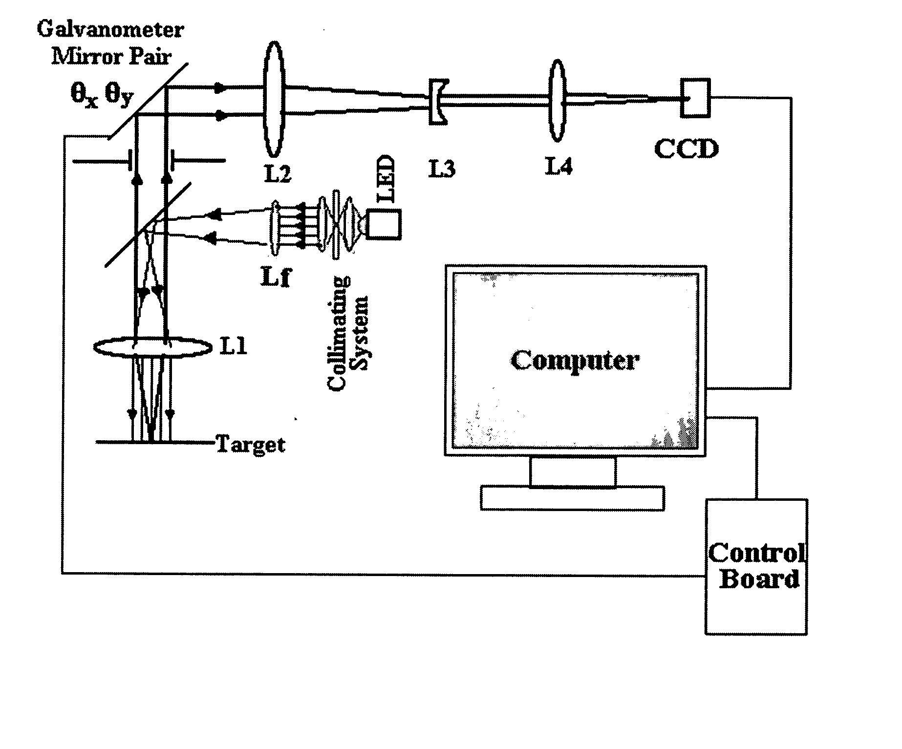
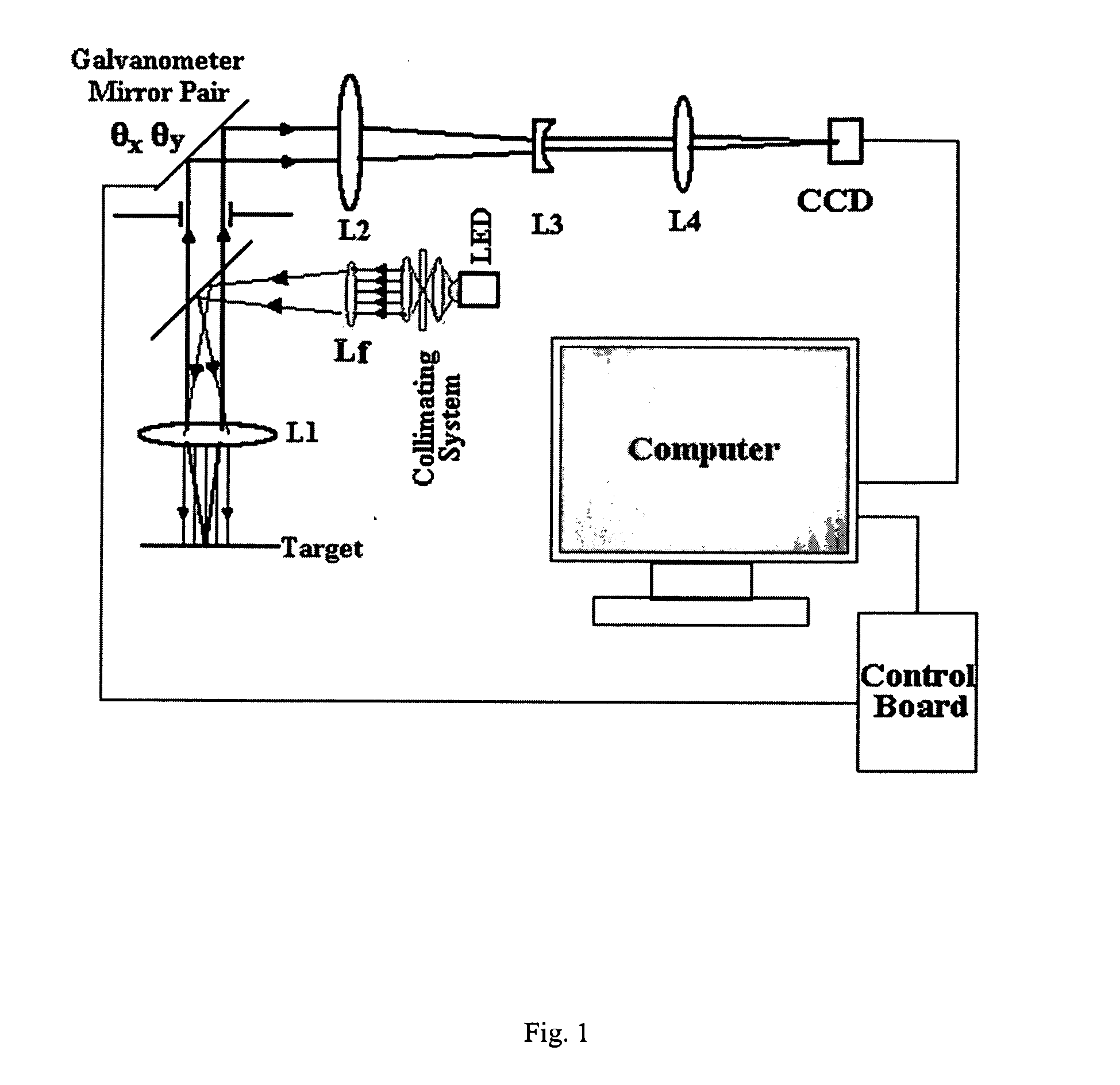
[0028] Referring now more specifically to the drawings, in which identical or similar parts are designated by the same reference numerals throughout, and first referring to FIG. 1, this figure is a schematic diagram of the microscope system.

[0029] The system consists of several parts: a light source, a scanning system, lenses, an imaging system, an computer controlling system and software. The light source consists of the LED, a diffuser and a collimating system. The scanning system consists of two one-dimensional galvanometers with mounted mirrors-such as the M-Series optical scanners by GSI Lumonics-scanning over the target in a prescribed pattern. The microscope part consists of an objective lens L1 (f=8 mm, D=8 mm), an imaging Lens L4 (f=30 mm, D=15 mm) and a Galilean-type optical system (5 times ratio) seated between L1 and L4 to condition the image according to the required performance such as the desired magnification and the CCD active area size. The target is placed at the...


PUM


Abstract

The computer-controlled optical scanning high magnification microscope imaging system with a large field of view disclosed herein overcomes a previous inability to achieve simultaneous high magnification and large field of view in microscopes. The subject imaging system includes galvanometer scanners, a CCD camera and high brightness LED sources at different wavelengths for rapid acquisition of a large number of high-resolution segmented tile images with a magnification of 800× each. The numerous segmented tiles combine to form a larger viewing field of the target, resulting in a compound image with an effective enlarged viewing area of 1.6×1.2 mm2. The speed and sensitivity of the system make it suitable for high resolution image monitoring of a small segmented area of dimensions 320×240 μm2 with a 4 μm resolution. The microscope can zoom in on each segment of the target without lost of resolution to attain a great degree of spatial detail. With its special capacities, this microscope would be beneficial to medicine, biology, semiconductor inspection, device analysis and quality control, as well as with multiphoton and fluorescence microscopes to image large fields with high resolution.

Description

CROSS-REFERENCE TO RELATED APPLICATION [0001] The subject application is based on Provisional Pat. Appln. No. 60 / 681,433 filed on May 17, 2005, the entire contents of which are incorporated by reference. This utility application is being filed within the statutory term for claiming priority based on a provisional application.BACKGROUND OF THE INVENTION [0002] 1. Field of the Invention [0003] This patent application generally relates to microscopes, in particular with an optical scanning zoom microscope that provides both high level of magnification and a wide range of view. [0004] 2. Description of the Prior Art [0005] Microscopes are important instruments capable of producing a magnified image of small objects on a micron scale. They are commonly used in many diverse scientific and industrial applications including manufacturing inspection and high-technology quality control in areas of cell research, tissue analysis, semiconductor inspection, devices analysis, biological and medic...

Claims


Application Information

Patent Timeline
Patent Type & Authority Applications(United States)
IPC IPC(8): G02B21/00
CPCG02B2207/114G02B21/0048
Inventor ALFANO, ROBERT R.WANG, CHUNSHUMYATSKY, PAVELZEVALLOS L., MANUEL E.
Owner ALFANIX TECH
Why Eureka
Try Eureka