High tenacity nonwoven fabric

a nonwoven fabric, high tenacity technology, applied in weaving, light beam reproducing, instruments, etc., can solve the problems of easy deformation and destruction of the structure of the nonwoven fabric, increased gaps among the fine fibers, and increased fine fibers, so as to ensure and stably conduct the

Active Publication Date: 2006-12-28
ASAHI KASEI FIBERS CORPORATION
View PDF7 Cites 24 Cited by
  • Summary
  • Abstract
  • Description
  • Claims
  • Application Information

AI Technical Summary

Benefits of technology

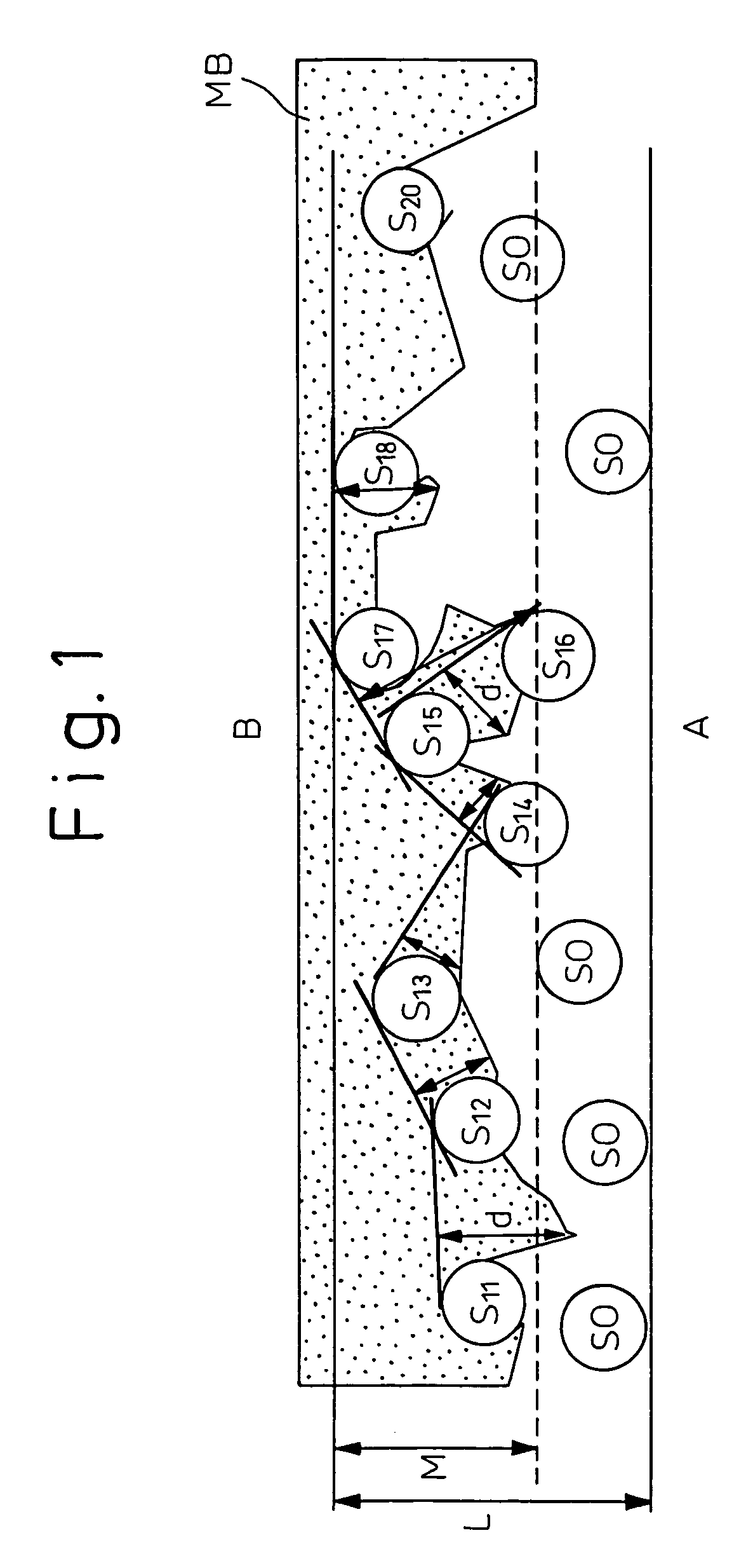
[0037] In the present invention, the intrusion index of the melt-blown fine fibers is expressed by the following formula (1):
[0038] That is, the intrusion index represents a degree of intimate mixing in terms of a filling degree of melt-blown fine fibers occupying filamentary fibers forming the filamentary fiber layer. The laminated three-layer nonwoven fabric of the invention is, therefore, characterized by the laminated nonwoven fabric structure including a filamentary fiber layer with which the melt-blown fine fibers are intimately mixed at a filling degree specified by an intrusion degree of the melt-blown fine fibers.
[0039] In the present invention, the laminated nonwoven fabric has a structure in which the melt-blown fine fibers are intimately mixed with the continuous filamentary fibers when the melt-blown fine fibers are intruded into the continuous filamentary fibers at an intrusion index of 0.36 or more. The intrusion index is more preferably 0.4 or more. Although a continuous filamentary fiber web is further placed on the melt-blown fine fiber layer, the melt-blown fine fibers intrude less in this direction.
[0040] Calculation of an intrusion index is carried out while portions that are embossed during thermocompressive bonding are being excluded. Thermally embossed portions are excluded from objects the intrusion index of which is to be evaluated, for the following reasons. It is concluded from electron microscopic observation of thermocompressively bonded embossed portions that fine fibers and filamentary fibers in the portions are mostly melted or fused under high pressure, and the fiber structure is destroyed. As a result, determination of a degree of intimate mixing of both types of fibers from observation of the cross-sectional shape of the portions is difficult.
[0041] In the present invention, the fiber diameter of the continuous filamentary fibers forming the spun-bonded filamentary fiber layer is 7 μm (0.53 dtex for PET, 0.42 dtex for Ny6) or more, preferably 12 μm or more in view of the covering properties and mechanical strength the filamentary fiber layer is required to have, and the spinning stability in the production process of spun-bonded fibers. Moreover, the upper limit is 20 μm or less. Because the continuous filamentary fiber layer is a web

Problems solved by technology

Moreover, the nonwoven fabric structure is relatively easily deformed and destroyed and, for example, the gaps among the fine fibers are expanded when a solid or a fluid to be filtered penetrates and is passed.
Furthermore, because the melt-blown nonwoven fabric having a low basis of weight is easily deformed significantly, and its handling is complicated, the fine structure is likely to be elongated in the course of pr

Method used


Image

  • High tenacity nonwoven fabric
  • High tenacity nonwoven fabric
  • High tenacity nonwoven fabric

Examples


examples

[0064] Examples of the present invention will be explained below. However, the present invention is in no way restricted thereto.

[0065] Specific properties referred to in examples and comparative Examples were obtained by the procedures described below.

[0066] (1) Measurements of Diameter (>m) of Fibers (Fiber Diameter)

[0067] Both ends, each 10 cm long, of a sample such as a fiber web and a nonwoven fabric are removed. A test piece, 1 cm×1 cm, is cut out from each region 20 cm wide of the fabric. The fiber diameter at 30 points of each test piece is measured with a microscope, and the average value of the measured values is calculated (numerical value beyond the first place of decimals being rounded). The average value is defined as the fiber diameter of the constituent fibers of the sample.

[0068] Apparatus used: VT-8000 (trade name, manufactured by KEYENCE Co., Ltd.)

[0069] Magnification in measurements: 1,000× for continuous filamentary fibers, and 2,500× for melt-blown fine fi...

examples 1 to 4

[0105] A filamentary fiber group of a polyethylene terephthalate for general purposes was extruded toward a transfer collecting face by spin bonding at a spinning temperature of 300° C., and spun at a spinning rate of 3,500 m / min. The spun fibers were adequately opened by corona charging in a charging amount of about 3 μC / g to give an unbonded filamentary fiber web composed of filaments that had an average fiber diameter of 13 μm and having a basis of weight of 25 g / m2 (5 cm variation of basis of weight of 15% or less (uniformity)), on a collecting net face.

[0106] On the other hand, a polyethylene terephthalate having a solution viscosity ηsp / C of 0.50 was spun by melt blowing at a spinning temperature of 300° C. and a heating air temperature of 320° C. with injection air of 1,000 Nm3 / hr / m to give a random web of extremely fine fibers (average fiber diameter of 1.6 μm) having a basis of weight of 10 g / m2. The random web was directly injected toward the above filamentary fiber web. ...

examples 5 to 8

[0113] Stacked three-layer webs (SW2 / MW / SW1) prepared under the same conditions as in Examples 1 to 4 were thermocompressively bonded while the emboss temperature was varied so that the tear tenacities in the MD direction attained given values. Laminated three-layer nonwoven fabrics in which the structures were fixed were thus prepared. Table 2 shows the properties for use of the nonwoven fabrics.


PUM

PropertyMeasurementUnit
Temperatureaaaaaaaaaa
Lengthaaaaaaaaaa
Lengthaaaaaaaaaa

Abstract

The present invention provides a laminated nonwoven fabric wherein the nonwoven fabric is a laminated one formed by integrating, through compressive bonding, a stacked nonwoven fabric structure comprising an upper and a lower thermoplastic synthetic filamentary fiber layer that have a fiber diameter from 7 μm or more to 20 μm, and an intermediate layer composed of thermoplastic synthetic fine fibers that have a fiber diameter of 5 μm or less, the laminated nonwoven fabric having an intimately mixed structure in which a portion of the fine fibers is intruded into at least one face side of the filamentary fiber layers with an intrusion index of 0.36 or more to bond, surround or interlace the filamentary fibers, a METSUKE of from 10 g or more to 250 g/m2, and a bulk density of 0.20 g/cm3 or more. The spun-bonded laminated nonwoven fabric of the present invention is a nonwoven fabric material that has durable various filtering and barriering functions exhibited by the fine fiber layer forming the nonwoven fabric structure, and that is far more excellent in tensile tenacity than the corresponding spun-bonded nonwoven fabric.

Description

TECHNICAL FIELD [0001] The present invention relates to an improved spun-bonded laminated nonwoven fabric excellent in tensile tenacity and having good filtering and barrier properties. [0002] The improved spun-bonded laminated nonwoven fabric of the present invention is a nonwoven fabric excellent in tensile tenacity and having filtering and barrier properties. The laminated nonwoven fabric can be used for various applications that particularly utilize the characteristics of the spun-bonded filamentary fiber nonwoven fabric, for example, building materials such as house wraps, wall materials and roof materials, sound insulation materials and sound absorbing materials, filtering materials such as food filters, air filters, liquid filters, filters for cleaners and membrane substrates, industrial and agricultural materials including filter materials firstly, sanitary and medical treatment materials such as personal protective equipment, disposable diapers, sterilization wraps and medi...

Claims


Application Information

Patent Timeline
IPC IPC(8): B32B5/26D04H1/56D04H5/00D04H1/549D04H1/55D04H1/559D04H5/06D04H13/00
CPCB32B5/022Y10T428/26B32B5/26B32B2250/03B32B2250/20B32B2262/0215B32B2262/0261B32B2262/0276B32B2307/102B32B2307/306B32B2307/54B32B2307/728B32B2410/00B32B2419/04B32B2419/06B32B2437/02B32B2553/00B32B2555/02B32B2571/00D04H13/003Y10S428/903Y10T428/27B32B5/06D04H1/559D04H1/56D04H3/14Y10T442/614Y10T442/62Y10T442/621Y10T442/659Y10T442/666Y10T442/68Y10T442/697B32B37/10B32B7/022
Inventor SUZUKA, RYUJINAKAKITA, MITSUJI
Owner ASAHI KASEI FIBERS CORPORATION
Why Eureka
Try Eureka