Circuit and method for receiving and mixing radio frequencies in a direct conversion receiver
a technology of direct conversion receiver and receiver, which is applied in the direction of multi-frequency-changing modulation transference, demodulation, electrical equipment, etc., can solve the problems of secondary intermodulation distortion, dcr has some problems, secondary intermodulation distortion generated by mixer, etc., to improve the linearity of the mixing circuit and improve the quality of the receiving circuit. , the effect of reducing the secondary intermodulation distortion
- Summary
- Abstract
- Description
- Claims
- Application Information
AI Technical Summary
Benefits of technology
Problems solved by technology
Method used
Image
Examples
embodiment 1
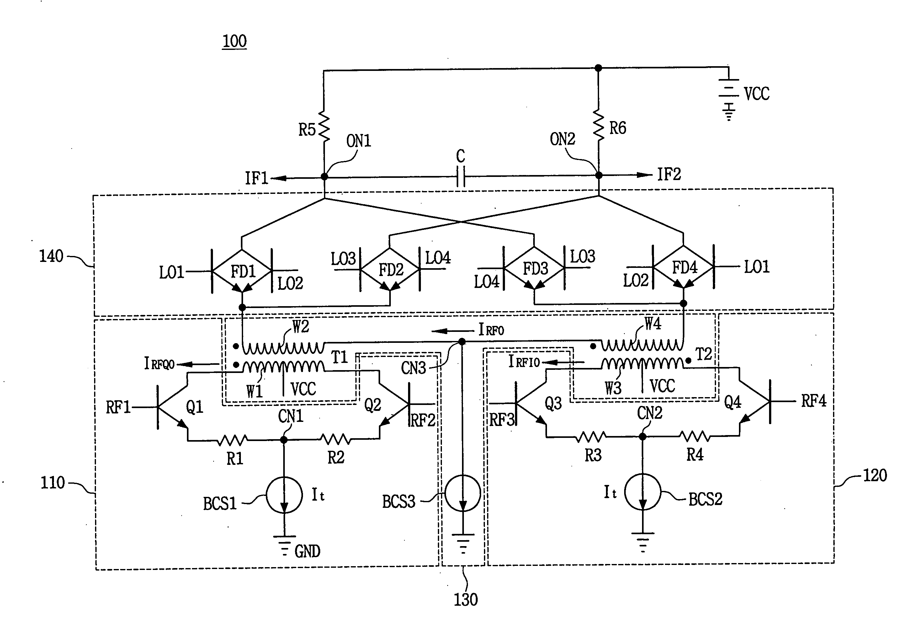
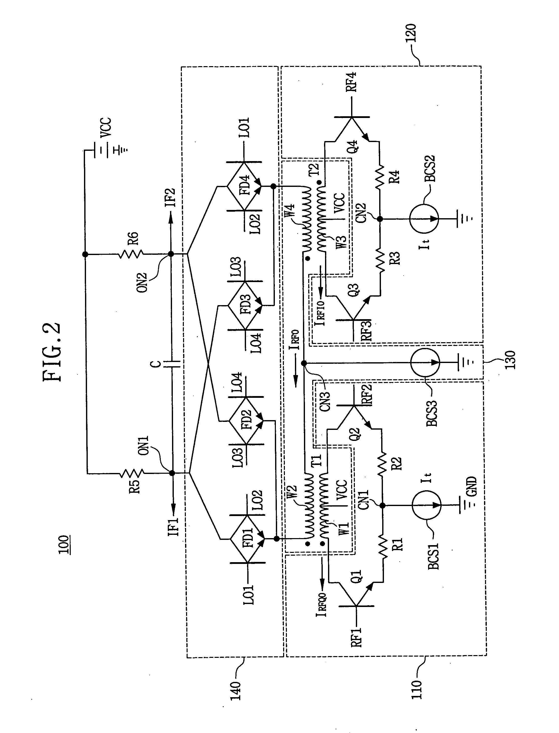
[0045]FIG. 2 is a circuit diagram of a harmonic rejection mixing circuit according to a first embodiment of the present invention.
[0046] Referring to FIG. 2, a frequency mixing circuit 100 comprises a first differential amplifier 110, a second differential amplifier 120, a subtracter 130 and a mixer 140.
[0047] The first differential amplifier 110 has a pair of an emitter coupled transistors Q1 and Q2 that are emitter coupled at first common node CN1. The first transistor Q1 has a base receiving a first input signal RF1 and the second transistor Q2 has a base receiving a second input signal RF2. The first input signal RF1 and the second input signal RF2 are 180° out of phase with respect to each other, and become a first pair input signals. The first differential amplifier 110 generates a first amplified signal IRFQO by amplifying the first pair input signals RF1 and RF2. A first bias current source BCS1 is connected between the first common node CN1 (of the emitter coupled transis...
embodiment 2
[0062]FIG. 3 is a circuit diagram of a harmonic rejection mixing circuit according to a second embodiment of the present invention.
[0063] A frequency mixing circuit shown in FIG. 3 has the same configuration as the first embodiment of the frequency mixing circuit as shown in FIG. 2, except for the mixer 240. Therefore, in FIG. 3, the same reference numerals denote the same elements in FIG. 2, and thus the detailed description of the same elements will be omitted.
[0064] Referring to FIG. 3, the mixer 240 has a double balanced mixing circuit including a Gilbert cell circuit. Thus, the frequency of drive signals L01 and L02 is the same as the frequency of input signals RF1, RF2, RF3 and RF4.
[0065] A first pair of emitter coupled transistors Q5 and Q6 has emitters commonly connected to each other and connected to one terminal of the second winding W2. The collector of one of the first pair of emitter coupled transistors Q5 and Q6 is connected to the first output node ON1, and the col...
embodiment 3
[0067]FIG. 4 is a circuit diagram of a harmonic rejection mixing circuit according to a third embodiment of the present invention.
[0068] Referring to FIG. 4, a frequency mixing circuit 400 has a differential amplifier 410. The differential amplifier 410 amplifies a first pair of input signals RF1 and RF2 in order to output a first current signal IRF1 and a second current signal IRF2. =A current to flow at a first node N1 into transistor Q13 is the first current signal IRF1 and a current to flow at a second node N2 into transistor Q14 is the second current signal IRF2. The differential amplifier 410 has a pair of emitter coupled transistors Q13 and Q14 and a bias current source BCS7. Transistor Q13 has a collector connected to the first node N1, a base receiving the first input signal RF1 having 0° phase, and an emitter connected a common node CN4 via a regeneration resistor R7. Transistor Q14 has a collector connected to the second node N2, a base receiving the second input signal ...
PUM
 Abstract
Description
Claims
Application Information
 - R&D
- Intellectual Property
- Life Sciences
- Materials
- Tech Scout
- Unparalleled Data Quality
- Higher Quality Content
- 60% Fewer Hallucinations
Browse by: Latest US Patents, China's latest patents, Technical Efficacy Thesaurus, Application Domain, Technology Topic, Popular Technical Reports.
© 2025 PatSnap. All rights reserved.Legal|Privacy policy|Modern Slavery Act Transparency Statement|Sitemap|About US| Contact US: help@patsnap.com


