
Dynamic interactive region-of-interest panoramic/three-dimensional immersive communication system and method

a communication system and dynamic interactive technology, applied in the field of dynamic interactive region of interest panoramic/three-dimensional immersive communication system and method, can solve the problems of reducing the efficiency of the system, and not being desirable in all instances, so as to reduce or remove the distortion of wide-angle objective lens

Inactive Publication Date: 2007-01-04
RITCHEY KURTIS J
View PDF7 Cites 43 Cited by
  • Summary
  • Abstract
  • Description
  • Claims
  • Application Information

AI Technical Summary

Benefits of technology

[0005] On the other hand, the spherical panoramic camera by Ritchey in 1992 was the first to simultaneously record a complete spherically panoramic scene on the recording surface of a single conventional rectangular shaped imaging device. The advantage of this was that only one camera was necessary, which lowered cost, device maintenance, weight, processing efficiency, and improved compactness. The limitation however, was that resolution was typically limited because an entire spherical scene was imaged on a single imaging device, which had limited resolution. When an entire panoramic scene was placed on the device only a small portion of the scene was devoted to any one place on the imaging device. So that when the scene was enlarged the resulting resolution was often low and pixilated. Of course the solution was to use a higher resolution sensor or film. But these alternatives also had limitations, like high sensor costs and developing and production costs.
[0007] In the years since those devices were built, higher resolution sensor costs have decreased. Additionally, image-processing capabilities have improved. Application requirements have changed also. For instance, in most live personal telepresence applications only the portion of the panoramic scene the user wants to view needs be recorded, processed, and communicated at any one time, not the entire scene as was done in some of the examples discussed above. Switching and multiplexing systems have been used to accomplish this when using a plurality of cameras, but the above-mentioned limitations of using a plurality of cameras remained. Alternatively, devices to sample out or select an image segment, also referred to as a “Region of Interest” (ROI) from a single camera sensor have not existed until recently. And until the present invention sampling out a plural number of ROI, or “Regions-of-Interest (ROIs) from a single frame had not been used in connection with fisheye lenses to provide imagery for building or panning a spherical field-of-view scene. Recent and developing printed circuit board and micro-chip technology allow for both imaging and associated processing of the image to be accomplished in a compact manner.
[0009] In the present invention a specially designed fiber optic imaging assembly to reduce or remove wide-angle objective lens distortion of an image(s) taken by the spherical field-of-view camera used with ROI processing has not been described until the present invention. This embodiment is advantageous because it provides an image derived from a panoramic camera that is better suited for ROI processing. The combination of these devices facilitates a more efficient system for applications such as telepresence and immersive gaming.
[0010] Alternatively, another method of reducing or removing wide-angle objective lens distortion of an image(s) is by the use of software or firmware. The software or firmware is included as part of the processing means. The processing means operates on the information included in tables and / or algorithms which are applied to the ROI image(s) in order to remove the image distortion. Unlike previous systems in which the entire image panoramic scene was transmitted to the processor and then the image segment to be viewed was selected and read-out, in the present system only the image segment(s), ROI's, to be viewed is / are read-out from the camera and associated conjunctive camera processing means. Thus processing is determined prior to read out from the camera and prior to transmission. And preferably, the image segment may also be operated upon to remove distortion and to stitch the image together for viewing prior to transmission to a remote location. This method of image manipulation is advantageous because it dramatically reduces bandwidth transmission requirements for transmitting panoramic imagery to remote communication.

Problems solved by technology

While it is beneficial in some instances to simultaneously record a complete scene about a point, it is not desirable in all instances.
A limitation of using a plurality of cameras is the requirement to simultaneously transmit, process, and store a large amount of information.
And in these instances a limitation is the cost of buying multiple camera systems.
Additionally, a limitation is that multiple cameras increase the weight and size of the panoramic camera system.
Additionally, a limitation is there are more components that can break.
Additionally, a limitation is plural cameras must be placed adjacent to one another pushing the actual objective taking lenses of each camera outward from a center point which causes adjacent subject stitching problems due to each lenses widely different points-of-view.
The limitation however, was that resolution was typically limited because an entire spherical scene was imaged on a single imaging device, which had limited resolution.
So that when the scene was enlarged the resulting resolution was often low and pixilated.
But these alternatives also had limitations, like high sensor costs and developing and production costs.
A limitation of both panoramic camera systems using single high-resolution camera or a plurality of cameras was that a reading out the signal or signals from the systems took up a very large bandwidth.
Reading this bandwidth from the panoramic camera system and processing the output has been a limitation of theses systems.
In the years since those devices were built, higher resolution sensor costs have decreased.
Switching and multiplexing systems have been used to accomplish this when using a plurality of cameras, but the above-mentioned limitations of using a plurality of cameras remained.

Method used


Image

  • Dynamic interactive region-of-interest panoramic/three-dimensional immersive communication system and method
  • Dynamic interactive region-of-interest panoramic/three-dimensional immersive communication system and method
  • Dynamic interactive region-of-interest panoramic/three-dimensional immersive communication system and method

Examples


first embodiment

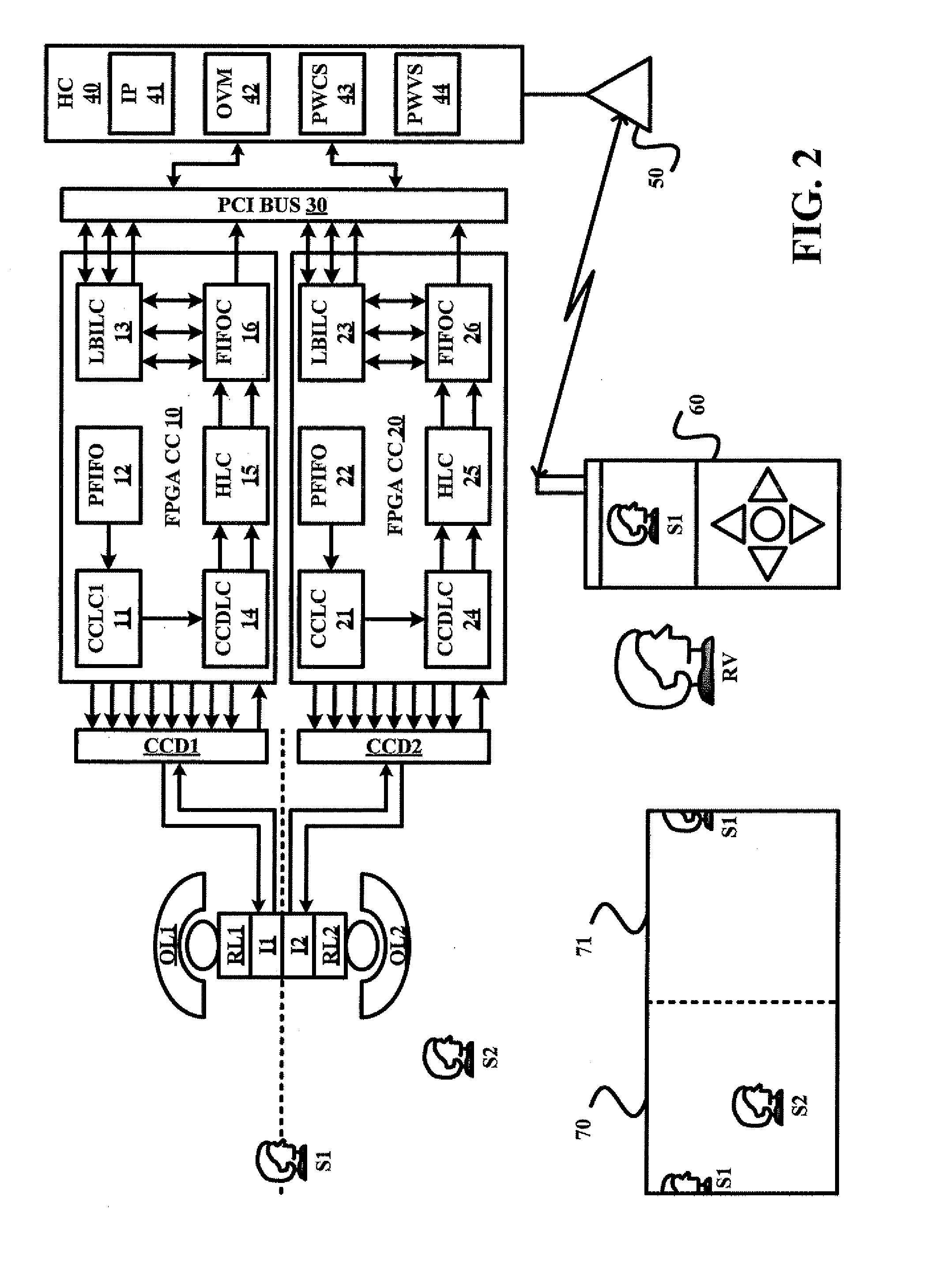
[0020] In the ROI system shown in FIG. 2, two 2K×2K sensors are placed back-to-back (like in FIG. 23 of the parent invention) and the region or regions of interest are dynamically and selectively addressed depending on the view defined by the users interactive control device. The sensors are addressable using software or firmware associated with the computer-processing portion of the system. The computer-processing portion of the system can be located in a housing worn by a user or in a device carried by a user for wireless applications. Still further, the computer processing means incorporate processing means of a host desktop or laptop. For instance the computer processing can be designed into a personal digital assistant (PDA) or a personal cellular phone (PCS) device (120). In order to save space the computer-processing portion of the system can comprise a Very Large Scale Integrated Circuit (VLSIC).

[0021] In FIG. 2 each objective lens group reflects a portion of the surrounding...

second embodiment

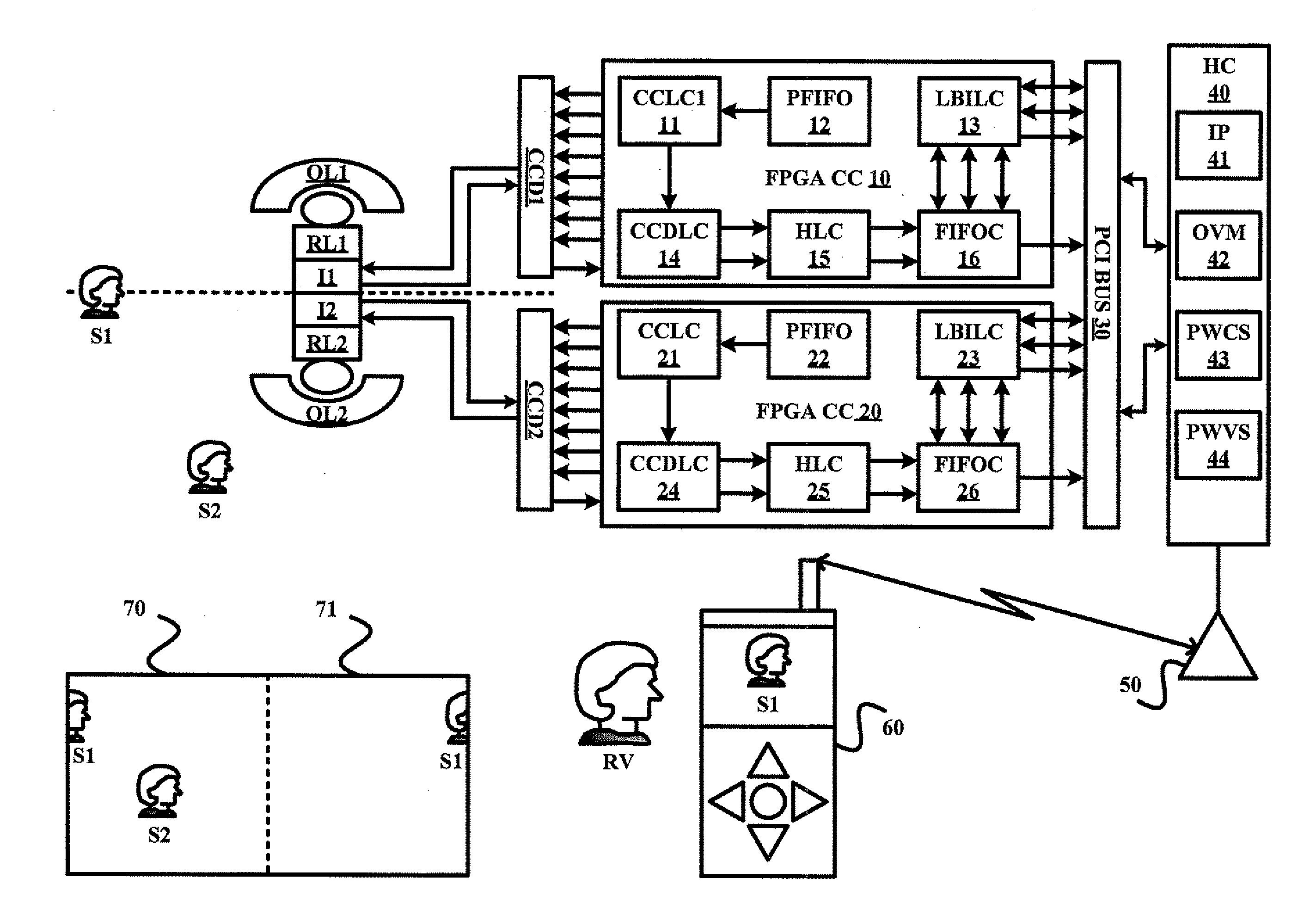
[0026] Alternatively, FIG. 3 shows the ROI system, wherein one 2K×2K imager is incorporated and off axis optical image relay means such as fiber optic image conduits, mirrors, or prisms are used to transmit images to a single CCD with ROI or plural ROI capabilities.

[0027] Instead of a plurality or multiplicity of ROI sensors like in FIG. 2, a single ROI sensor is incorporated in FIG. 2. In FIG. 3 a single charge-coupled-device (CCD) based high-speed imaging system, called a real-time, event-driven (RARE) camera, is illustrated. This camera is capable of readout from multiple sub-windows [also known as regions of interest (ROIs)] within the CCD field of view. Both the sizes and the locations of the ROIs can be controlled in real time and can be changed at the camera frame rate. The predecessor of this camera was described in “High-Frame-Rate CCD Camera Having Subwindow Capability” (NPO-30564) NASA Tech Briefs, Vol. 26, No. 12 (December 2002), page 26. The architecture of the prior ca...


PUM


Abstract

A method of dynamic interactive region-of-interest panoramic immersive communication involves a capturing a panoramic image and a specification of a size and a location of a region-of-interest in the panoramic image.

Description

RELATED APPLICATION DATA [0001] This application claims the benefit of U.S. Provisional Application Ser. No. 60 / 652,950 filed on Feb. 15, 2005.FIELD OF THE INVENTION [0002] In the same vain this invention has as its objective and aim to converge new yet uncombined technologies into a novel, more natural and user-friendly system for communication, popularly referred to today as “telepresence”, “visuality”, “videoality”, or “Image Based Virtual Reality” (IBVR). BACKGROUND OF THE INVENTION [0003] What the present invention teaches and is novel is integration of either “an event-driven random-access-windowing CCD-based camera” and tracking system developed by Steve P. Monacos, Raymond K. Lam, Angel A Portillo, Gerardo G. Ortiz; Jet Propulsion Laboratory, California Institute of Technology, taught in “smspie04.pdf” or / and the integration of “Large format variable spatial acuity superpixel imaging: visible and infrared systems applications” (ref. 11c above). by Paul L. McCarley, UAFRL, an...

Claims


Application Information

Patent Timeline
IPC IPC(8): H04N7/00
CPCH04N5/232H04N7/142H04N5/247H04N5/23238H04N23/60H04N23/698H04N23/90
Inventor RITCHEY, KURTIS J.
Owner RITCHEY KURTIS J
Learn More