Double-clad fiber scanning microscope

a scanning microscope and double-clad fiber technology, applied in the field of scanning microscopes, can solve the problems of limiting the application of scanning microscopes, affecting the scanning rate, and affecting the scanning rate, and achieve the effects of large field of view, high scanning rate, and wide field of view

Active Publication Date: 2007-01-04
RGT UNIV OF MICHIGAN
View PDF14 Cites 113 Cited by
  • Summary
  • Abstract
  • Description
  • Claims
  • Application Information

AI Technical Summary

Benefits of technology

[0004] Confocal microscopy was first invented by Marvin Minsky in 1957. Initially, stage scanning was employed to obtain an image by moving a specimen in a raster pattern across a focused point of a stationary light beam. An exit pinhole is placed in the image plane conjugated to the spot being scanned so that only the signal originating from the focused spot is transmitted through the pinhole, while out-of-focus signals are prevented from reaching a detection system. A confocal microscope therefore generally has a higher resolution than a wide-field microscope, and more importantly, it has sectioning capability to achieve a 3-D image. The benefit of stage scanning is that the field of view is vastly expanded, because the area that can be imaged is determined by the travel range of the scanning stage rather than the optics in the microscope. However, there are drawbacks that limit its application. The scanning rate is extremely slow because it requires time to translate the massive stage precisely. In addition, a moving stage causes vibration problems to samples, especially liquid-bathed biological samples. These problems were circumvented when laser scanning confocal microsc

Problems solved by technology

However, there are drawbacks that limit its application.
The scanning rate is extremely slow because it requires time to translate the massive stage precisely.
In addition, a moving stage causes vibration problems to samples, especially liquid-bathed biological samples.
Because the incident angle of the laser beam on the entrance pupil of an objective lens has to vary in a certain range, assoc

Method used


Image

  • Double-clad fiber scanning microscope
  • Double-clad fiber scanning microscope
  • Double-clad fiber scanning microscope

Examples


Embodiment Construction

[0013] The following description of the preferred embodiment is merely exemplary in nature and is in no way intended to limit the invention, its application, or uses.

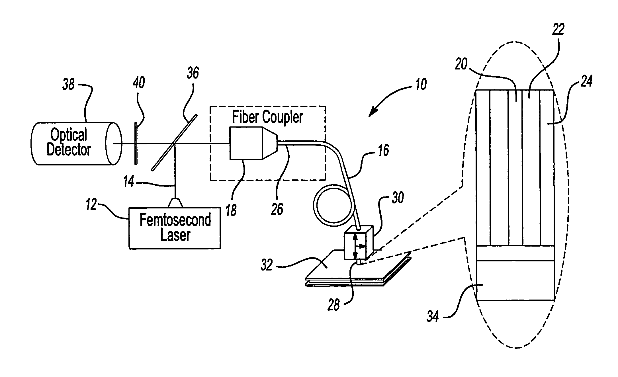
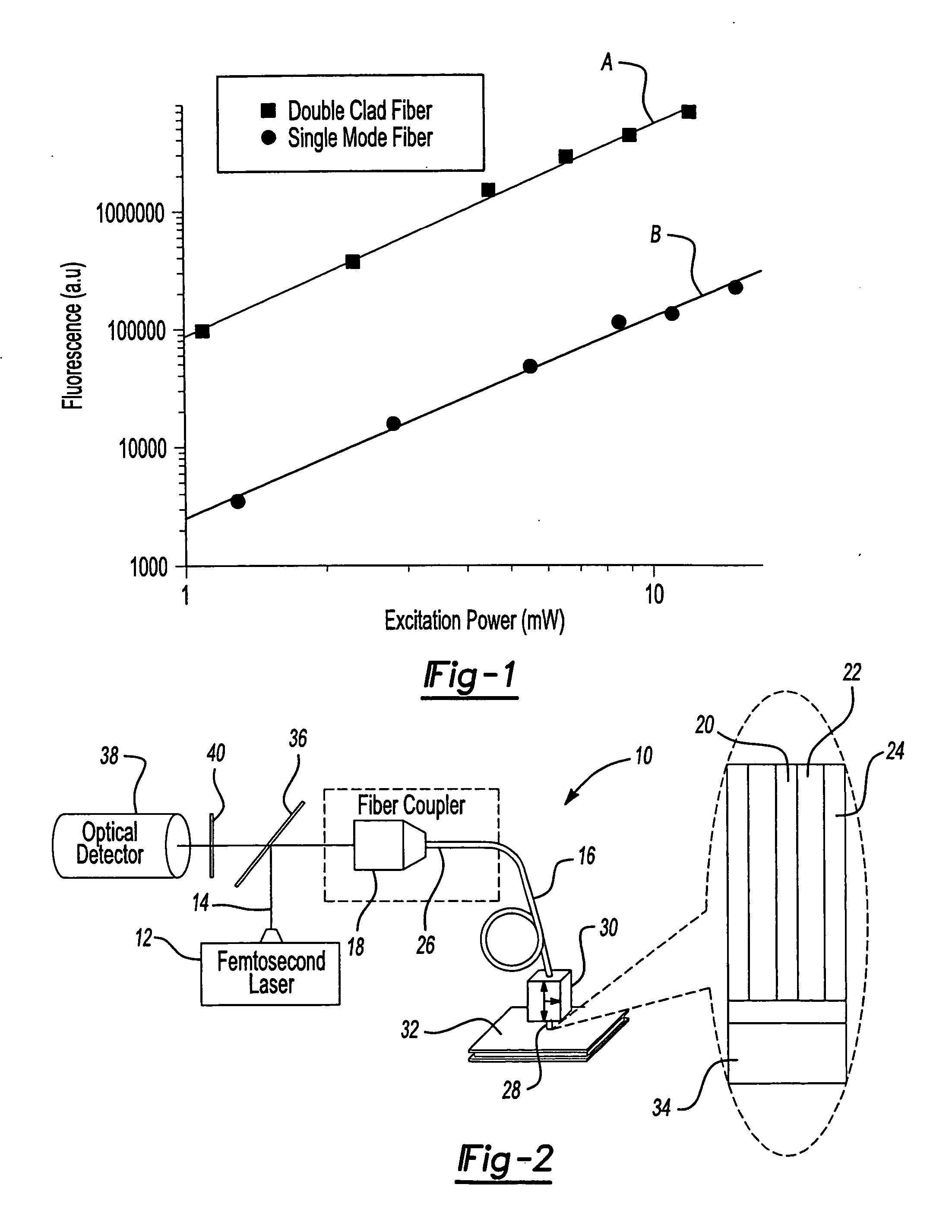
[0014] In contrast to conventional beam scanning, which includes changing the angle of an incident beam at an objective lens, the beam scanning of the present invention can be achieved by moving an optical fiber, which delivers a laser beam for excitation and collects signals back along the same fiber. Conventional fibers, either single-mode or multimode fibers, cannot be practically used in this way. Although a single-mode fiber (SMF) has an acceptable mode for excitation, the numerical aperture (NA) is typically only about 0.1, which results in a very inefficient signal collection. On the other hand, although a multimode fiber multimode fiber has a larger numerical aperture that is good for collecting signals, the output mode is unable to be tightly focused, thus resulting in inefficient excitation and low resolution...


PUM


Abstract

A scanning microscope having a laser outputting an excitation laser beam and a fiber member having a first core and a second core. The second core is generally disposed within the first core and is operable to receive the excitation laser beam from the laser and transmit the excitation laser beam to a sample to be tested. A moveable stage supports an end of the fiber member and/or a sample to be tested and is operable to move the end of the fiber member and the sample to be tested relative to each other.

Description

CROSS-REFERENCE TO RELATED APPLICATIONS [0001] This application claims the benefit of U.S. Provisional Application No. 60 / 474,113, filed on May 29, 2003. The disclosure of the above application is incorporated herein by reference.GOVERNMENT RIGHTS [0002] This invention was made with government support under Contract No. N01-CO-27173 awarded by the National Cancer Institute, National Institutes of Health. The Government has certain rights in the invention.FIELD OF THE INVENTION [0003] The present invention relates to scanning microscopes and, more particularly, to a scanning microscope using a double-clad fiber for improved detection efficiency. BACKGROUND AND SUMMARY OF THE INVENTION [0004] Confocal microscopy was first invented by Marvin Minsky in 1957. Initially, stage scanning was employed to obtain an image by moving a specimen in a raster pattern across a focused point of a stationary light beam. An exit pinhole is placed in the image plane conjugated to the spot being scanned ...

Claims


Application Information

Patent Timeline
IPC IPC(8): G02B21/00G01N21/65G02BG02B6/02G02B6/04G02B21/06
CPCG01N21/6458G01N2021/6484G01N2021/656G02B6/02042G02B6/02342G02B21/0076G02B6/03622G02B6/04G02B6/32G02B21/0024G02B6/02366G02B6/02G02B21/00G02B21/06
Inventor YE, JING YONGNORRIS, THEODORE B.
Owner RGT UNIV OF MICHIGAN
Why Eureka
Try Eureka