All fiber laser solution for spectral broadening and pulse stretching in a chirped pulse amplification fiber system

a fiber system and fiber laser technology, applied in the field of pulsed fiber laser systems, can solve the problems of increasing the footprint affecting the performance of the whole system, so as to reduce the high order dispersion, reduce the footprint of the laser system, and reduce the effect of high-order dispersion

Active Publication Date: 2007-01-04
POLARONYX
View PDF9 Cites 13 Cited by
  • Summary
  • Abstract
  • Description
  • Claims
  • Application Information

AI Technical Summary

Benefits of technology

[0006] It is therefore an aspect of the present invention to provide a photonics crystal fiber spliced with a common single mode fiber for broadening the bandwidth by self phase modulation (SPM) thus increasing the stretching ratio such that the length of fiber for pulse stretching can be significantly reduced.
[0007] It is another aspect of this invention that the reduced stretching fiber length can also reduce the distance between the components of the grating compressor, thus the physical dimension of the system can be significantly reduced. Reduction of physical size of a fiber system is achievable to increase the compactness that leads to significantly improved robustness, stability and reliability.
[0009] It is a further aspect of this invention to provide special mode matching splicing by applying a mode adapter for splicing the PCF with a common single mode fiber such that the SPM function of the SPF can be optimized. The mode adapting function provided by the mode adapter thus greatly enhancing the pulse stretching process thus reducing the required fiber length and resolves the problems and limitations of the TOD and higher order dispersions.
[0010] It is a further aspect of this invention that the manipulation of the optical spectrum in the CPA fiber amplifier achieves the purpose of reducing the higher order dispersions. For the coherent broadband short pulse, the spectral domain and the temporal domain are closely correlated. The non-linearity can modify the spectral phase, generate new spectral component; it largely improves the capability of the generation of a high-energy short pulse from the fiber laser system. This invention suggests a novel avenue to control the pulse compressibility by changing the spectral properties thus reducing the high order dispersion.
[0012] In a preferred embodiment, this invention further discloses a method for reducing the high order dispersion, shrinking the laser system footprint. This scheme is realized in an all fiber solution with a simple implementation. The system is very compact, reliable, robust and stable.

Problems solved by technology

Even though current technologies of fiber laser have made significant progress toward achieving a compact and reliable fiber laser system providing high quality output laser with ever increasing output energy, however those of ordinary skill in the art are still confronted with technical limitations and difficulties.
However, due to the small dispersion in the commonly available standard mode fibers and the relatively narrow bandwidth outputted directly from the fiber mode locking oscillator, a stretcher has to be implemented with long fiber.
A fiber stretcher with longer length introduces additional problems due to a larger amount of third order dispersion.
A long fiber stretcher also requires a compressor with longer length of grating pair for de-chirping, that requires large footprint of the whole system.
A long fiber stretcher may further cause potential problems of system robustness, reliability and stability.
While such a large stretching ratio is good for the control of nonlinear effect in the fiber amplifier chain, it is also leads to a serious problem due to the fact that it leaves large third-order dispersion uncompensated.
The uncompensated TOD causes additional problems to the fiber laser system because the uncompensated third order dispersion (TOD) affects the compressibility of the amplified pulses.
Actually, for current existing and demonstrated high-energy fiber laser system, the uncompensated TOD is a main issue, which makes it very difficult to achieve <200 fs high-energy pulses output.

Method used


Image

  • All fiber laser solution for spectral broadening and pulse stretching in a chirped pulse amplification fiber system
  • All fiber laser solution for spectral broadening and pulse stretching in a chirped pulse amplification fiber system
  • All fiber laser solution for spectral broadening and pulse stretching in a chirped pulse amplification fiber system

Examples


Embodiment Construction

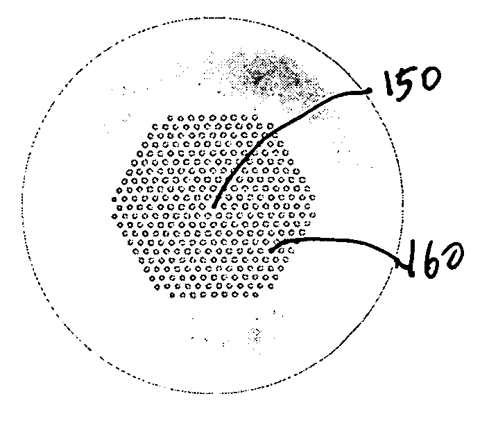
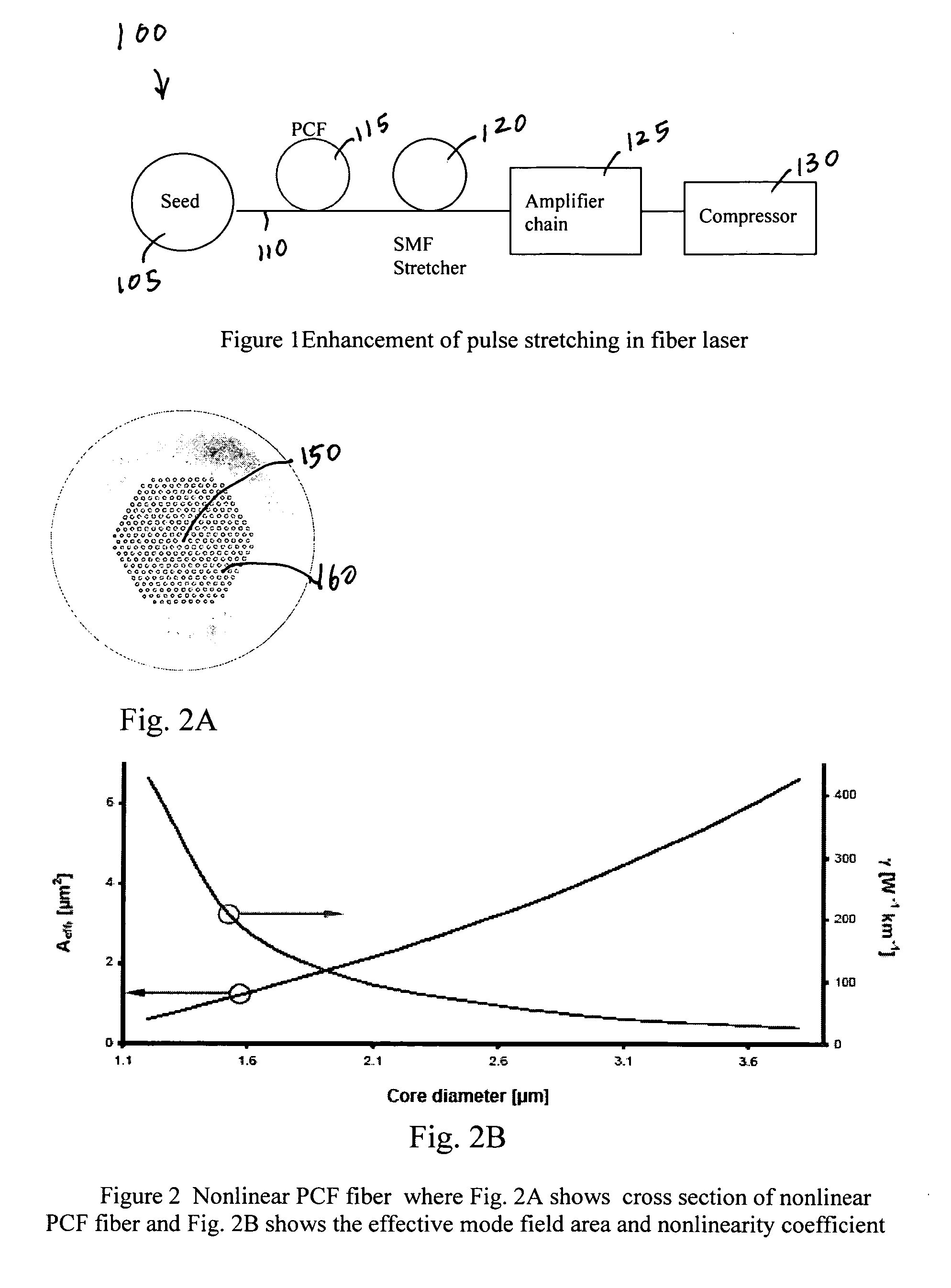
[0018] Referring to FIG. 1 for a schematic diagram of a fiber laser system 100 of this invention that implements a common single mode fiber sliced with a photonics crystal fiber (PCF) for enhancement of the spectral broadening and pulse stretching functions of the fiber laser system. The laser system 100 includes a laser seed 105 that includes an oscillator for generating a fiber-based mode-locking laser with an original pulse duration. The laser project from the oscillator of the seed laser 105 has a laser pulse energy of the order of 0.1 nJ level. A common single mode fiber 110 is spliced with a photonics crystal fiber (PCF) 115. In an exemplary embodiment, the PCF 115 may be a PCF from Crystal Fiber, Demark. The purpose of splicing the PCF 115 to the common single mode fiber 110 is to generate large bandwidth via self phase modulation (SPM). Since the single mode PCF 115 has a small field-mode diameter (˜1.5 um), the SPM can be very large, and the bandwidth can be broadened to 10...


PUM


Abstract

A fiber Chirped Pulse Amplification (CPA) laser system includes a fiber mode-locking oscillator for generating a laser for projecting to a fiber stretcher for stretching a pulse width of the laser wherein the stretcher further comprising a self-phase modulation (SPM) assisted photonics crystal fiber (PCF) single mode (SM) fiber stretcher. The fiber CPA laser system further includes a multistage amplifier for amplifying the laser and a high-order dispersion-compensating compressor for compensating high order dispersions and compressing the pulse width of the laser.

Description

[0001] This Formal Application claims a Priority Date of Jun. 30, 2005 benefit from two Provisional Patent Applications 60 / 696,372 and Jul. 1, 2005 benefit from another Provisional Patent Application 60 / 696,275 filed by the same Applicant of this Application. The disclosures made in 60 / 696,372 and 60 / 696,275 are hereby incorporated by reference in this Patent Application.FIELD OF THE INVENTION [0002] The present invention relates generally to apparatuses and methods for providing pulsed fiber laser systems. More particularly, this invention relates to a system configuration for the enhancement of stretching ratio in a conventional fiber stretcher in high-energy short pulse fiber laser. BACKGROUND OF THE INVENTION [0003] Even though current technologies of fiber laser have made significant progress toward achieving a compact and reliable fiber laser system providing high quality output laser with ever increasing output energy, however those of ordinary skill in the art are still conf...

Claims


Application Information

Patent Timeline
Patent Type & Authority Applications(United States)
IPC IPC(8): H01S3/30H01S3/10H01S3/13
CPCH01S3/0057H01S3/067H01S3/2308H01S3/06741H01S3/06754H01S3/06725
Inventor LIU, JIANXIA, JIANGFAN
Owner POLARONYX
Why Eureka
Try Eureka