
Developing roller including carbon nanotubes for electrophotographic device and method for fabricating the developing roller

Active Publication Date: 2007-01-04
HEWLETT PACKARD DEV CO LP
View PDF25 Cites 15 Cited by
  • Summary
  • Abstract
  • Description
  • Claims
  • Application Information

AI Technical Summary

Benefits of technology

[0013] It is therefore a first object of the present invention to provide a development roller including carbon nanotubes for an electrophotographic device that is capable of producing a high quality of an image by implementing a low hardness and a low resistance.
[0014] It is a second object of the present invention to provide a method of fabricating a development roller including carbon nanotubes for an electrophotographic device that is capable of producing a high quality of an image by implementing a low hardness and a low resistance.

Problems solved by technology

However, This type has the disadvantage of a high drift in resistance of the roller in response to low temperate and low wet circumstance and high temperature and high wet circumstance.
This type also has difficulty in implementing low resistance, and has image defects due to movements of molecules which have not been cross-linked onto the surface of the roller.
However, when the excessive carbon black is added so as to implement the desired low resistance, a hardness of the roller body increases to add extra weight to a toner stress, which in turn rapidly degrades the toner durability to weaken the roller durability, so that a life time of the development roller is shortened.
In addition, dispersibility of the carbon black is degraded to cause the resistance value to lack uniformity.
In addition, the carbon black as fine particles flows out of the roller body to contaminate the inside of the electrophotographic device and the images.

Method used


Image

  • Developing roller including carbon nanotubes for electrophotographic device and method for fabricating the developing roller
  • Developing roller including carbon nanotubes for electrophotographic device and method for fabricating the developing roller
  • Developing roller including carbon nanotubes for electrophotographic device and method for fabricating the developing roller

Examples


embodiment

[0066] Fabrication of the body of the development roller

example 1

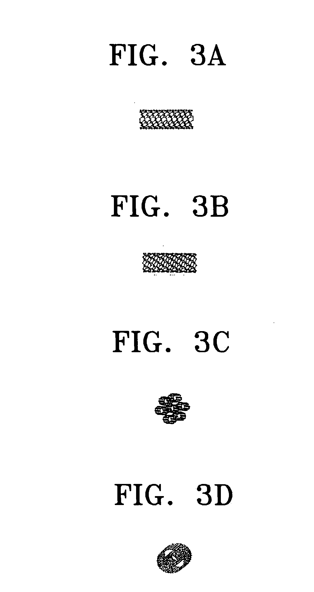
[0067] The diisocyanate was sealed and kept in a cold storage to be dehydrated before use, and a mixture of 1,4-methylene diisocyanate and toluene diisocyanate was used for the same. The liquid polyether polyol was vacuum-dried and dehydrated for about one day in a vacuum oven at a temperature of 90° C. The carbon nanotube was a single wall type nanotube fabricated by an Arc discharge process. The carbon nanotubes had a degree of purity of 40 vol. % to 90 vol. %, a diameter of 1 nm to 1.2 nm, and a length of 5 μm to 20 μm. First, 1 mol of polyether polyol and carbon nanotube in an amount of 0.4 phr were mixed by a prepolymer method in a reaction container at an reaction temperature of 75° C. The prepolymer was mixed with an amine based accelerator in an amount of 0.5 mol, and 0.525 mol of diisocyanate was injected thereto four times.

[0068] 1,4-butandiol of 1 mol was then injected.

[0069] The resulting prepolymer containing the carbon nanotubes was then placed into the mold shaped i...

example 2

[0071] The same method was used as in Example 1 except that the carbon nanotube was used in an amount of 0.6 phr instead of 0.4 phr of the first embodiment, to fabricate the thermoplastic polyurethane roller body containing carbon nanotubes.


PUM


Abstract

A development roller for electrophotographic device and a method of making the development roller are disclosed. The development roller according to the present invention includes a central shaft and a roller body. The roller body is composed of an elastic polymer material as a primary material and carbon nanotubes in an amount to provide the conductivity of the roller body. According to the present invention, the development roller can exhibit a low hardness and a low resistance at the same time, produce images having high sharpness, and does not contaminate images.

Description

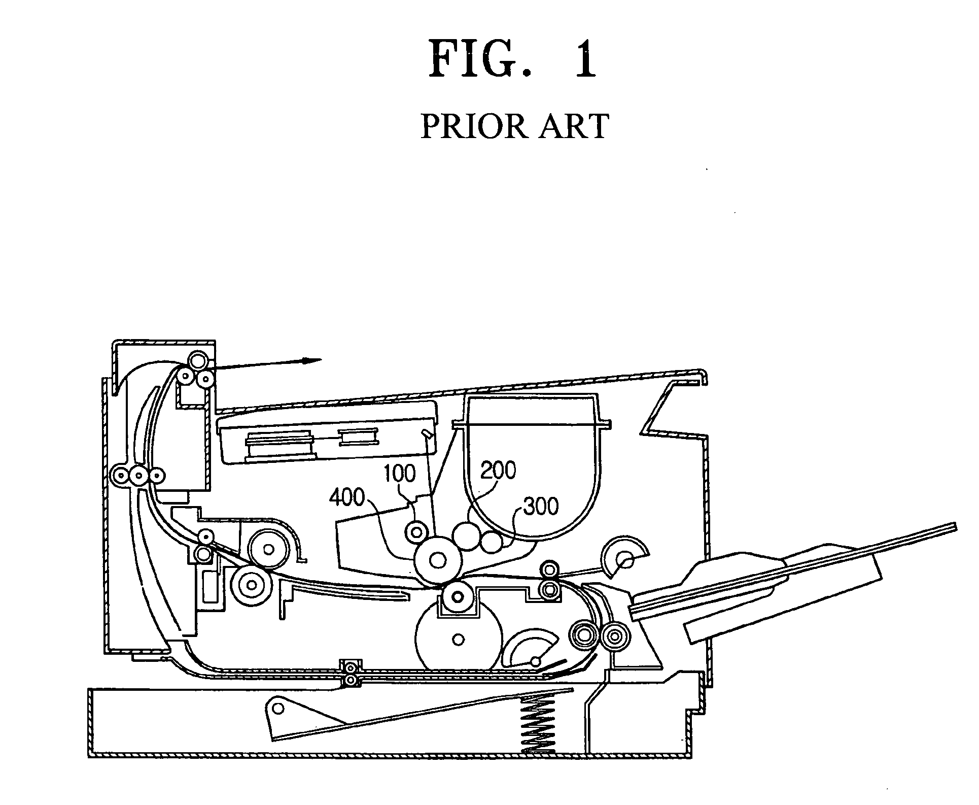
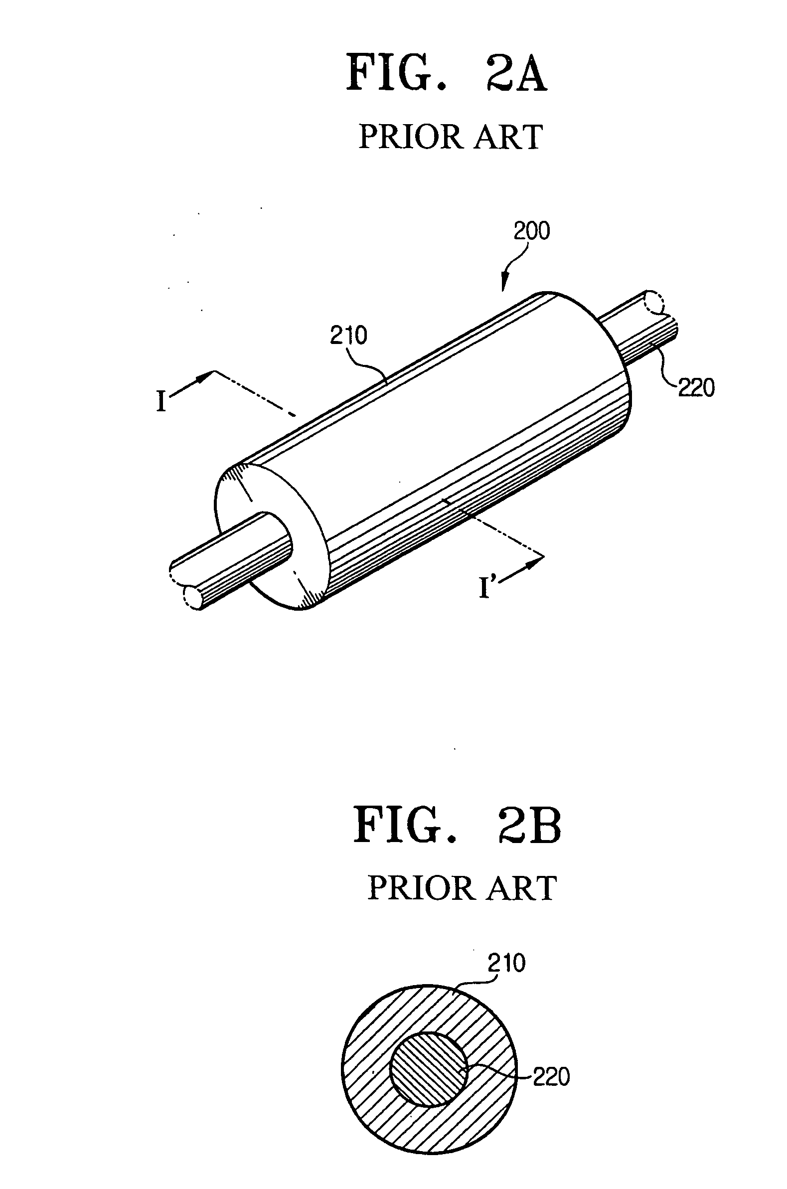
CROSS-REFERENCE TO RELATED APPLICATION [0001] This application claims benefit under 35 U.S.C. § 119(a) of Korean Patent Application No. 2005-54476, filed Jun. 23, 2005 in the Korean Intellectual Property Office, the entire contents of which are hereby incorporated by reference. BACKGROUND OF THE INVENTION [0002] 1. Field of the Invention [0003] The present invention relates to a development roller. In particular, the invention is directed to a development roller including carbon nanotubes for an electrophotographic device capable of maintaining sharpness of an image while keeping a low resistance and the development roller elastic. [0004] 2. Description of the Related Art [0005] Examples of the electrophotographic device include a copy machine, a printer, a facsimile, a composite apparatus, and so forth. [0006]FIG. 1 shows a laser printer among those examples, FIG. 2A shows a development roller of the laser printer shown in FIG. 1, and FIG. 2B is a cross-sectional view of FIG. 2A. T...

Claims


Application Information

Patent Timeline
IPC IPC(8): G03G15/08
CPCG03G15/0818G03G15/06B82Y30/00G03G2215/025
Inventor KIM, IN
Owner HEWLETT PACKARD DEV CO LP
Learn More