Method for processing hydrocarbon pyrolysis effluent

a technology of hydrocarbon pyrolysis and effluent, which is applied in the direction of hydrocarbon oil cracking process, hydrocarbon oil treatment products, thermal non-catalytic cracking, etc., can solve the problems of inability to use conventional heat exchangers, inability to separate relative small amounts of tar from water cracking, and inability to achieve satisfactory steam cracking techniqu

Inactive Publication Date: 2007-01-11
EXXONMOBIL CHEM PAT INC
View PDF43 Cites 20 Cited by
  • Summary
  • Abstract
  • Description
  • Claims
  • Application Information

AI Technical Summary

Benefits of technology

[0028] Typically, the gaseous effluent is cooled in step (a) to a temperature of less than about 371° C. (700° F.), cooled in step (c) to a temperature of less than about 316° C. (600° F.), and cooled in step (e) to a temperature of less than about 100° C. (220° F.), e.g., the gaseous effluent is cooled in step (a) to a temperature ranging from about 204° to about 316° C. (400 to 600° F.), cooled in step (c) to a temperature ranging from about 93° to about 232° C. (2000 to 450° F.), and cooled in step (e) to a temperature ranging from about 15° to about 93° C. (60° to 200° F.), say

Problems solved by technology

As a result, heat exchangers can efficiently recover most of the valuable heat without fouling and the relatively small amount of tar can be separated from the water quench albeit with some difficulty.
This technique is, however, not satisfactory for use with steam crackers that crack naphthas and heavier feedstocks, collectively referred to as liquid crackers, since liquid crackers generate much larger quantities of tar than gas crackers.
Below this temperature, conventional heat exchangers cannot be used because they would foul rapidly from accumulation and thermal degradation of tar on the heat exchanger surfaces.
Moreover, the larger quantity of heavy oils and tars produced by liquid cracking would render water quench operations ineffective, making it difficult to remove heat from the condensed water and to dispose of excess quench water and the heavy oil and tar in an environmentally acceptable manner.
The primary fractionator, however, is a very complex piece of equipment that typically includes an oil quench section, a primary fractionator tower and one or more external oil pumparound loops.
The primary fractionator with its associated pumparounds is the most expensive component in the entire cracking system.
Heat

Method used


Image

  • Method for processing hydrocarbon pyrolysis effluent
  • Method for processing hydrocarbon pyrolysis effluent

Examples


Embodiment Construction

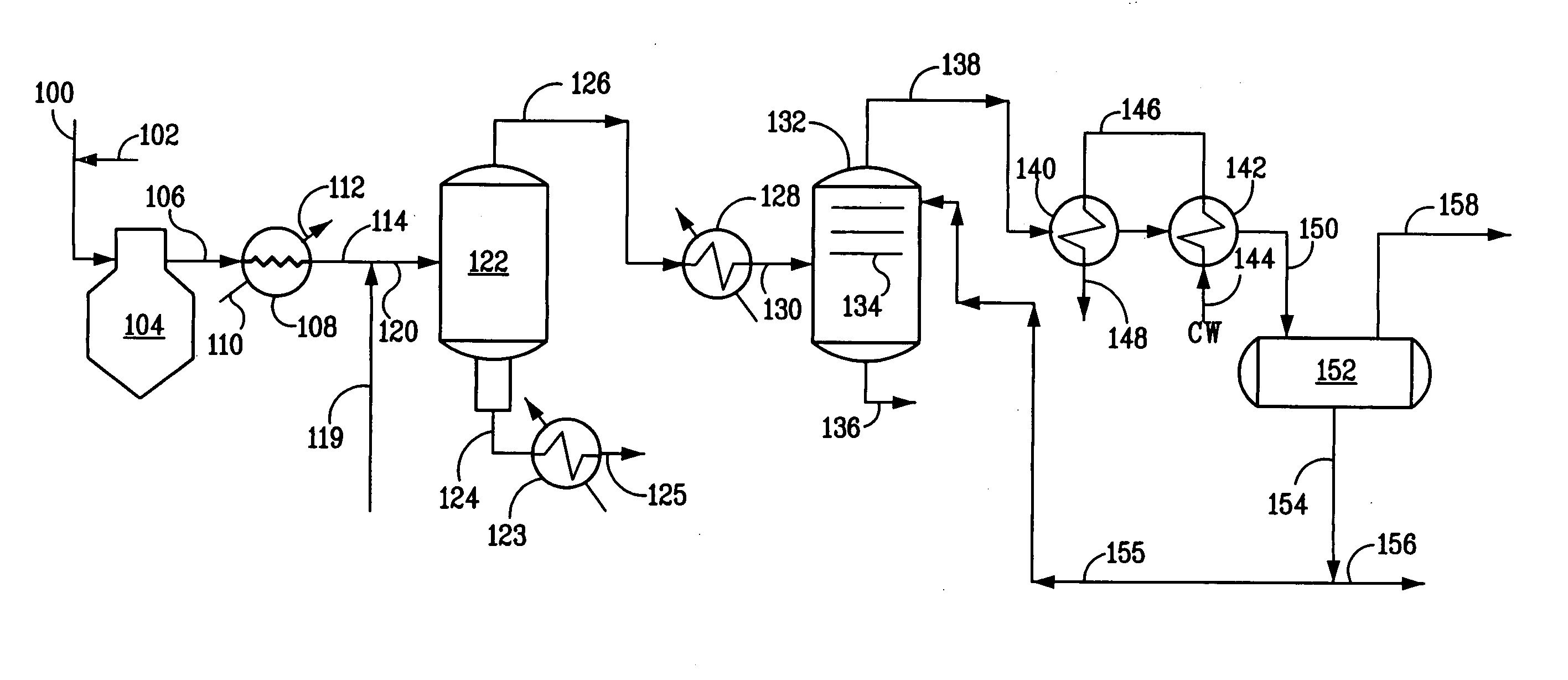
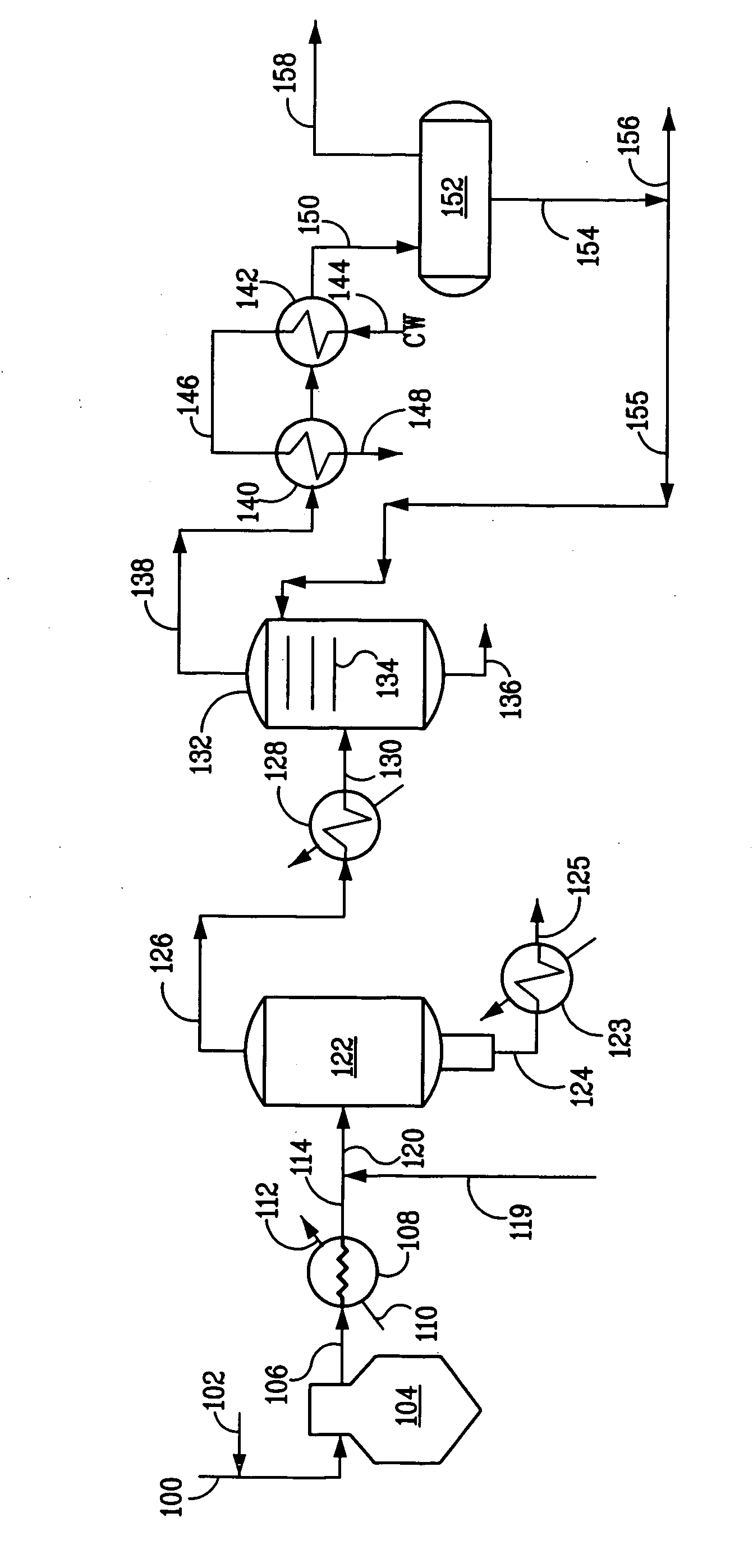
[0049] The present invention provides a low cost way of treating the gaseous effluent stream from a hydrocarbon pyrolysis reactor so as to remove and recover heat therefrom and to separate C5+ hydrocarbons, providing separate pyrolysis gasoline and gas oil fractions (which may be suited to use as a quench oil), as well as the desired C2-C4 olefins in the effluent, without the need for a primary fractionator.

[0050] Typically, the effluent used in the method of the invention is produced by pyrolysis of a hydrocarbon feed boiling in a temperature range, say, from about 40° to about 704° C. (104° to 1300° F.), such as naphtha or gas oil. For example, the effluent used in the method of the invention is produced by pyrolysis of a hydrocarbon feed having a final boiling point above about 180° C. (356° F.), such as feeds heavier than naphtha. Such feeds include those boiling in the range from about 177° to about 538° C. (350° to 1000° F.), say, from about 204° to about 510° C. (400° to 950...


PUM


Abstract

A method and apparatus are disclosed for treating the effluent from a hydrocarbon pyrolysis unit employing a small primary fractionator, i.e., a rectifier. The method comprises cooling the gaseous effluent, e.g., by direct quench and/or at least one primary heat exchanger, and then cooling the gaseous effluent to a temperature at which tar, formed by reactions among constituents of the effluent, condenses, e.g., in a secondary exchanger. The resulting mixed gaseous and liquid effluent is passed through a rectifier, to cleanly separate quench oil from the gaseous effluent comprising a pyrolysis gasoline fraction, whose boiling point can be lowered as a result of the rectifier treatment. The effluent is then cooled to condense a liquid effluent comprising pyrolysis gasoline and water condensed from steam, which fractions are separated in a distillate drum. The cooled gaseous effluent is directed to a recovery train to recover light olefins. At least a portion of the pyrolysis gasoline-containing fraction can be recycled to the rectifier to enhance separation of the quench oil from the pyrolysis gasoline fraction.

Description

CROSS-REFERENCE TO RELATED APPLICATIONS [0001] The present application expressly incorporates by reference herein the entire disclosures of Ser. No. ______ Attorney Docket No. 2005B060, entitled “METHOD FOR PROCESSING HYDROCARBON PYROLYSIS EFFLUENT”, Ser. No. ______ Attorney Docket No. 2005B061, entitled “METHOD FOR COOLING HYDROCARBON PYROLYSIS EFFLUENT”, Ser. No. ______ Attorney Docket No. 2005B062, entitled “METHOD FOR PROCESSING HYDROCARBON PYROLYSIS EFFLUENT”, Ser. No. ______ Attorney Docket No. 2005B063, entitled “METHOD FOR PROCESSING HYDROCARBON PYROLYSIS EFFLUENT”, and Ser. No. ______ Attorney Docket No. 2005B065, entitled “METHOD FOR PROCESSING HYDROCARBON PYROLYSIS EFFLUENT”, all of which are incorporated herein by reference and concurrently filed with the present application.FIELD OF THE INVENTION [0002] The present invention is directed to a method for processing the gaseous effluent from hydrocarbon pyrolysis units, especially those units utilizing feeds that are heavi...

Claims


Application Information

Patent Timeline
IPC IPC(8): C10G9/00B01J8/04B01J10/00C10G15/00
CPCC10G9/002C10G2300/301C10G2400/02C10G2300/805C10G2300/4081
Inventor STRACK, ROBERT DAVIDMESSINGER, JOHN R.
Owner EXXONMOBIL CHEM PAT INC
Why Eureka
Try Eureka