
Wide range power supply

a power supply and wide-range technology, applied in the direction of electric variable regulation, process and machine control, instruments, etc., can solve the problems of bulky and expensive power supply, impractical voltage generation of current power supply configuration, and inability to provide high output voltage precision, etc., to achieve high overall operating efficiency

Active Publication Date: 2007-01-11
BIO RAD LAB INC
View PDF9 Cites 68 Cited by
  • Summary
  • Abstract
  • Description
  • Claims
  • Application Information

AI Technical Summary

Benefits of technology

[0009] Accordingly, embodiments of the present invention provide methods, apparatus, and systems capable of delivering from less than 20V to more than 5000V. A power supply in accordance with the embodiments of the present invention uses switch mode technology to achieve high overall operating efficiency and is capable of operating from no load to full load without loss of regulation. The power supply in accordance with the embodiments of the present invention operates directly from the utility supply (e.g., 110V / 220V and 50 Hz / 60 Hz).
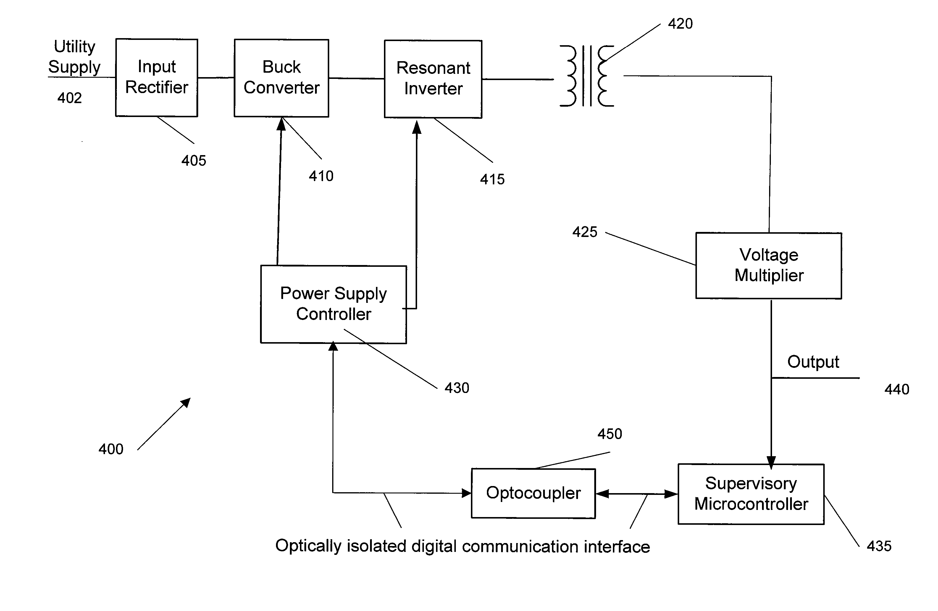
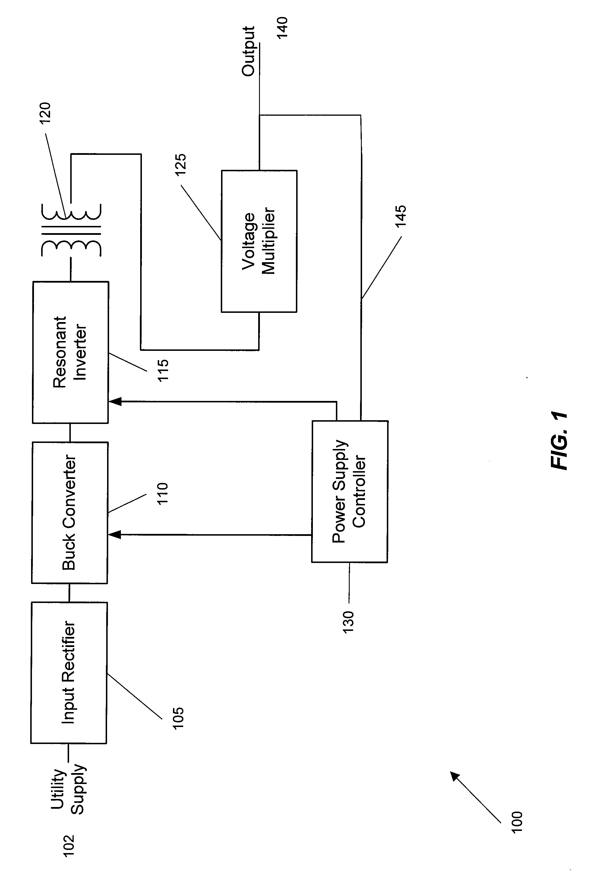
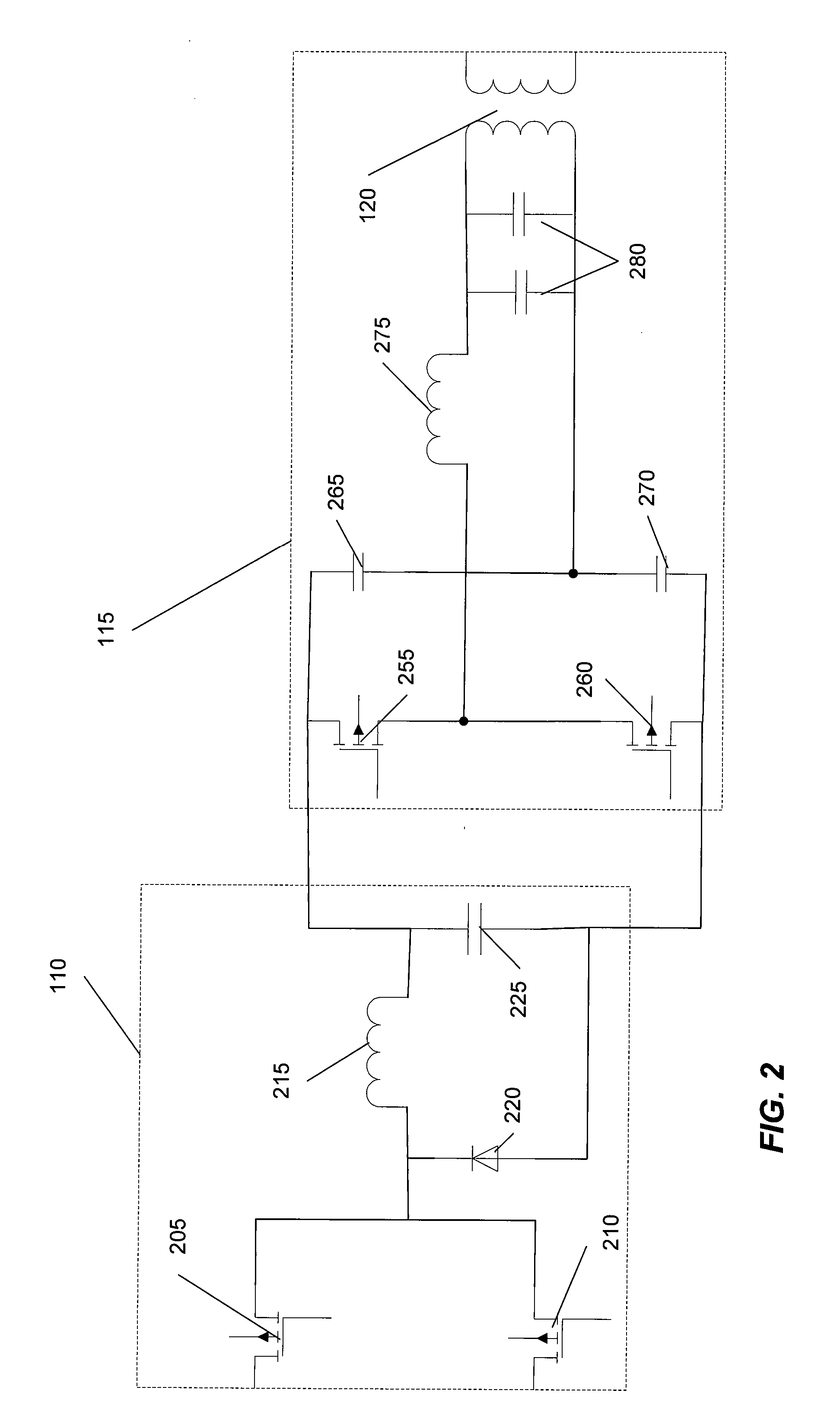
[0011] The dc / dc converter may be a buck converter, a buck-boost converter, or other suitable dc / dc converter. The resonant inverter may be a quasi-resonant inverter, which can have different designs, such as a half-bridge or an H-bridge. Also, other inverters may be used, such as resonant pole inverters, resonant dc link inverter, or resonant snubber inverters. One embodiment of the present invention uses a transformer with single secondary winding and smooth waveforms due to resonant switching which generate relatively lower EMI and hence reduce the cost of EMI filter network employed. In another embodiment, the voltage multiplier also acts as a rectifier of a signal from the transformer.
[0020] In yet another exemplary embodiment of the present invention, a power supply in accordance with embodiments of the present invention uses a fully digital control architecture. Control is achieved through a power supply controller, which may be a digital signal processor (DSP). The digital architecture enables the control to adapt to the changing load conditions. In a conventional architecture where the power converter control is analog and the supervisory functions are controlled by a microprocessor, the converter control is prone to time and temperature drift. The pure digital architecture makes the control system generally time and temperature invariant. In one embodiment, the control architecture uses three processors. The three processors use an optically isolated interface to communicate using a unique protocol for communication that enables reliable operation in a noisy environment such as a switching power supply.

Problems solved by technology

Current power supply configurations are impractical for achieving voltages as high as 5000V and do not provide high precision in the output voltage.
The many windings required for such high voltages create a bulky and expensive power supply.
A flyback configuration, as well as other switching power supplies, also suffer from high electromagnetic interference (EMI) as follows.
Thus, increased filtering is needed, which results in a higher cost of the end product.
Also, the large number of windings on a flyback transformer causes poor coupling of magnetic flux between the primary and the secondary windings.
This results in a higher leakage flux, which requires the additional cost of higher radiated EMI filtering.
Running at high power, flyback transformers also generate relatively higher common mode EMI, which reduces efficiency of the power conversion stage.
The precision of current power supply configurations is also limited by the current switching and regulation mechanisms.
For example, in a conventional architecture the power converter control is prone to time and temperature drift.
Additionally, galvanic isolation of input and output is a design need so as to meet product safety and regulatory requirements, and current feedback patterns within using isolation circuitry produce offset errors and non-linearities.

Method used


Image

  • Wide range power supply
  • Wide range power supply
  • Wide range power supply

Examples


Embodiment Construction

[0033] Embodiments of the present invention provide a wide range power supply capable of delivering 20V to 5000V. The power supply in accordance with the embodiments of the present invention uses switch mode technology to achieve high overall operating efficiency and is capable of operating from no load to full load without loss of regulation. The power supply may operate directly from the utility supply (e.g., 110V / 220V and 50 Hz / 60 Hz).

[0034] Unless defined otherwise, all technical and scientific terms used herein have the meaning commonly understood by a person skilled in the art to which this invention pertains. As used herein, the following acronyms are defined as follows: constant current (CC); constant voltage (CV); constant power (CP); power factor correction (PFC); analog to digital converter (ADC); pulse width modulation (PWM); liquid crystal display (LCD); resistor capacitor series circuit (RC-circuit); inductor-capacitor (LC), digital signal processor (DSP), and electro...


PUM


Abstract

A wide range power supply capable of delivering 20V to 5000V is provided. The power supply of the present invention uses switch mode technology to achieve high overall operating efficiency and is capable of operating from no load to full load without loss of regulation. The power supply in accordance with the embodiments of the present invention operates directly from the utility supply (e.g., 110V / 220V and 50 Hz / 60 Hz). In one embodiment, the power supply's power conversion stage includes the following stages: an input rectifier; a buck converter; a quasi-resonant inverter; and a voltage multiplier. The above indicated stages are connected in series to achieve the large output voltage range. High precision is obtained from a use of a digital feedback loop, possibly in connection with an analog feedback loop.

Description

CROSS REFERENCES TO RELATED APPLICATIONS [0001] The present application claims the benefit of earlier filed provisional application U.S. Ser. No. 60 / 697,869, entitled “WIDE RANGE POWER SUPPLY FOR PROTEIN ELECTROPHORESIS, ISOELECTRIC FOCUSING AND ELECTROPHORETIC BLOTTING,” filed on Jul. 8, 2005, the entire content of which is incorporated by reference.BACKGROUND OF THE INVENTION [0002] The present invention is related to power supply systems, and more specifically to wide range power supply devices. Such devices are used, for example, in protein electrophoresis, isoelectric focusing, DNA sequencing, and electrophoretic blotting. [0003] Protein electrophoresis and isoelectric focusing demand power supplies that meet diverse requirements of delivering voltages from less than 20V to several kilovolts. Thus, these power supplies may be termed wide range power supplies. These power supplies also need to be efficient and able to perform in different modes such as the constant voltage, cons...

Claims


Application Information

Patent Timeline
Patent Type & Authority Applications(United States)
IPC IPC(8): H02M3/335
CPCH02M3/1588H02M3/33515Y02B70/1466Y02B70/1425Y02B70/1433H02M2001/007Y02B70/10H02M1/007
Inventor JOSHI, RAHULHUTSON, DON
Owner BIO RAD LAB INC
Learn More