
Thermally coupled monolith reactor

Inactive Publication Date: 2007-01-11
ZEROPOINT CLEAN TECH
View PDF11 Cites 45 Cited by
  • Summary
  • Abstract
  • Description
  • Claims
  • Application Information

AI Technical Summary

Benefits of technology

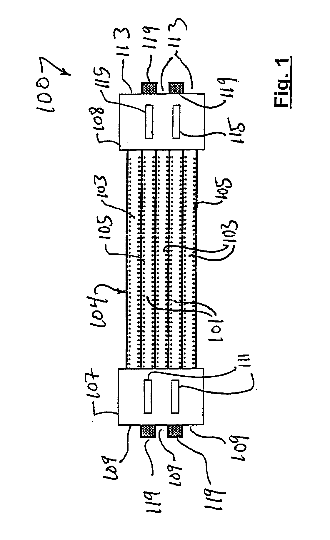
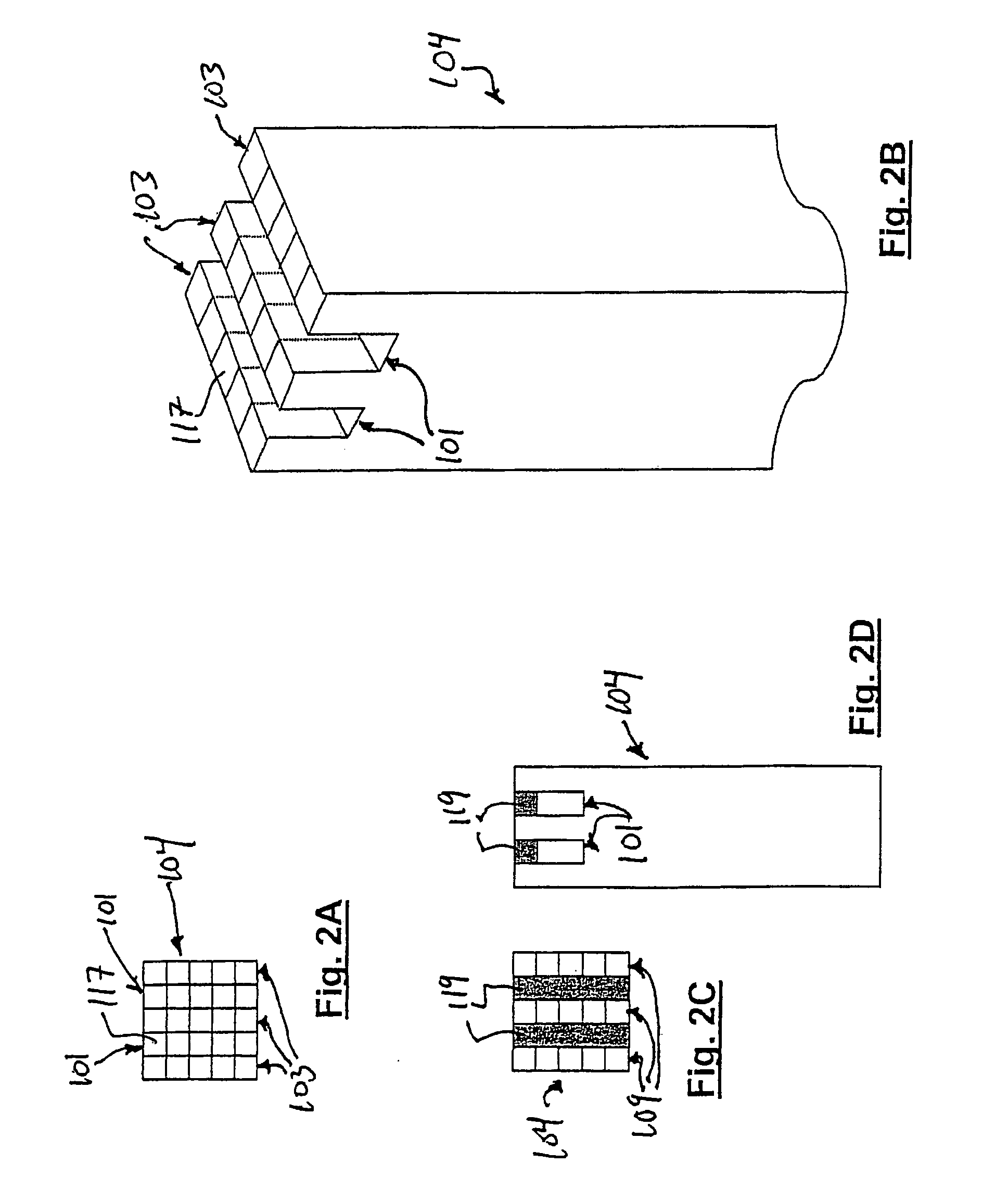
[0021] More particularly, the invention comprises, in one form, a monolith to which alternate channels have been sealed at opposing ends. A catalyst coating has been applied to the inner wall. A thin capillary like tube is passed through the inlet of the void and arranged such that it falls short of the sealed end. The opposing end is prepared in a similar manner. Process gas is passed through this tube to the far end of the monolith. The fluid exits the tube is directed back towards to inlet. As the fluid traverses the channel reaction occurs in the catalytically coated walls. Any heat which is required or generated by the process is transferred through the wall. However, even with this highly efficient transfer mechanism the gas will still absorb some heat energy and become hot. This heat energy can be conducted through the capillary inlet tube to preheat the incoming reactants. This arrangement alleviates the need for an external heat exchanger (although one can be used to provide further heating) and improvers the overall efficiency of the reactor.
[0023] Furthermore, the invention includes a method for enhancing one or more catalytic chemical reactions in terms of rate, product yield, energy and other parameters. Here, the initiating an exothermic reaction within one flow path of the monolithic reactor serves the dual purpose of creating a product yield as a result of that exothermic reaction and as a heat source. With the aid of this heat source, a second and endothermic reaction may be initiated in a secondary flow path which may absorb the heat from the exothermic reaction thereby enhancing product yield and making efficient use of available energy. To optimize the use of this heat, the reactions are controlled through one of many factors such as feed rate of the reactants, catalyst quality, reactant concentration and others. The flow paths may be cocurrent, countercurrent or other such variation as necessary to maximize heat transfer between the two reactions.

Problems solved by technology

However, even with this highly efficient transfer mechanism the gas will still absorb some heat energy and become hot.

Method used


Image

  • Thermally coupled monolith reactor
  • Thermally coupled monolith reactor
  • Thermally coupled monolith reactor

Examples


example 1

[0042] In this example, reaction 1 is the steam reforming of methane, expressed by Equation 2:

CH4+H2O⇄CO+3H2 ΔHf=206 kJ / mol   (2)

This fast and energetic process requires that a significant amount of energy be supplied to the catalyst to prevent the process from becoming thermally limited. This heat is to be supplied by reaction 2, which, in this example, is the catalytic oxidation of methane, expressed by Equation 3:

CH4+O2→CO2+H2O ΔHf=−800 kJ / mol   (3)

Approximately 0.25 mol of methane is combusted for each mol of methane processed. The overall process consists of first preheating the reactants to the required temperature. It ensures good thermal management for the products leaving the reactor to be used to preheat the incoming reactants to a temperature close to the reaction temperature. The methane, oxygen, and associated nitrogen (reaction 2) flow through the inlets 109 of the inlet manifold 107 and into the reaction channels 117 of the flow path 103. Heterogeneous oxidation...


PUM

PropertyMeasurementUnit
Thicknessaaaaaaaaaa
Flow rateaaaaaaaaaa
Shapeaaaaaaaaaa

Abstract

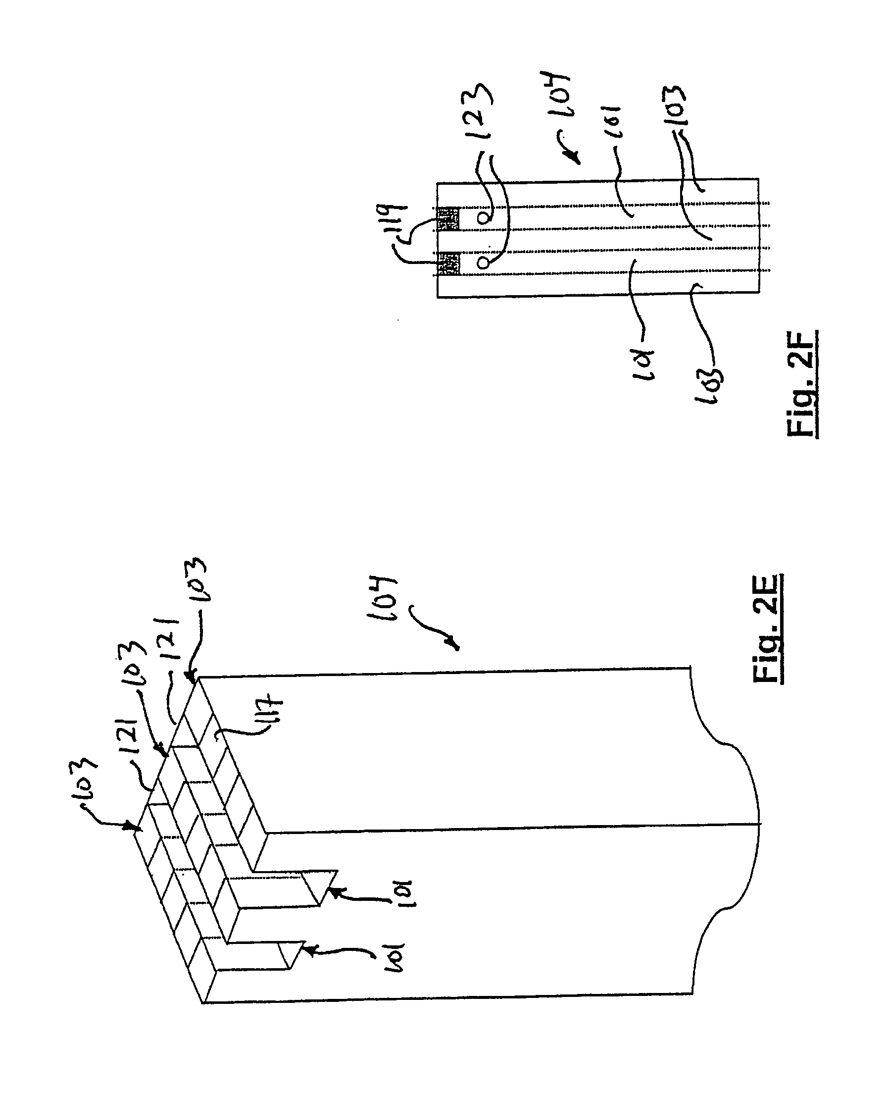
The invention comprises, in one form thereof, a chemical processing method to thermally contact an endothermic and an exothermic reaction without mixing the two streams, utilizing a thermally coupled monolith reactor (TCMR). A ceramic or metal monolith is modified to produce a structure containing at least two sets of discrete flow paths and which are separated by a number of common walls. Manifolds are arranged such that one reaction mixture flows through one set of channels and a different reaction mixture flows through the second. Catalytic material, which is active for the relevant reaction, is coated onto the inner walls of each of the sets of channels. The two reactions are chosen such that one is exothermic and one is endothermic, such that the energy required by the endothermic process is supplied directly through the dividing wall from the exothermic process occurring on the opposing side. This method of heat transfer completely decouples the gas phase hydrodynamics from the heat transfer process.

Description

PRIORITY CLAIM [0001] This application is based upon and claims priority to U.S. Provisional Patent Application No. 60 / 697,133, filed on Jul. 7, 2005, which is hereby incorporated by reference herein in its entirety.FIELD OF THE INVENTION [0002] This invention relates to a chemical reactor and thermal processing apparatus. BACKGROUND OF THE INVENTION [0003] Many chemical processes utilize catalysts to enhance chemical conversion behavior. A catalyst promotes the rate of chemical conversion but does not effect the energy transformations which occur during the reaction. A catalytic chemical reactor therefore must have a facility for energy to flow into or be withdrawn from the chemical process. Often catalytic processes are conducted within tubes which are packed with a suitable catalytic substance. The process gas flows within the tube and contacts the catalytic packing where reaction proceeds. The tube is placed within a hot environment such as a furnace such that the energy for the...

Claims


Application Information

Patent Timeline
IPC IPC(8): B01J8/02
CPCB01J12/007B01J2219/00117B01J19/2485
Inventor LEVESON, PHILIP D.
Owner ZEROPOINT CLEAN TECH
Learn More