Reconfigurable transmitter

a transmission system and reconfigurable technology, applied in the field of reconfigurable transmitters, can solve the problems of device saturation or cut-off, the highest power consumption of any single part of the transmitter, and the least efficient class of power amplifiers, so as to achieve flexible use and high efficiency of transmission.

Inactive Publication Date: 2007-01-18
NOKIA CORP
View PDF26 Cites 127 Cited by
  • Summary
  • Abstract
  • Description
  • Claims
  • Application Information

AI Technical Summary

Benefits of technology

[0019] It is an object of the invention to provide a highly efficient transmission device and method, by means of which flexible use in all type of transmission systems can be ensured.

Problems solved by technology

It typically also has the highest power consumption of any single part of the transmitter.
This leads to the least distortion, but results in the least efficient class of power amplifiers—the power amplifier's bias current must be high enough so that the input RF signal never forces the transistor into a non-linear region, e.g., in the case of a bipolar type transistor, causes the device to go into saturation or cut-off.
Non-linear, or switched-mode power amplifiers are unable to pass any signal containing amplitude modulation (AM) without massive distortion and spectral regrowth.
The bandwidth of the SMPS is however limited by the achievable switching speed.
However, switched-mode transmitters are also limited in terms of their dynamic range.
This dynamic range issue may be the most difficult problem to address in switched-mode transmitters, such as polar transmitters.
However, the power control range that is available from a polar transmitter might only be around 30 dB.

Method used


Image

  • Reconfigurable transmitter
  • Reconfigurable transmitter
  • Reconfigurable transmitter

Examples


Embodiment Construction

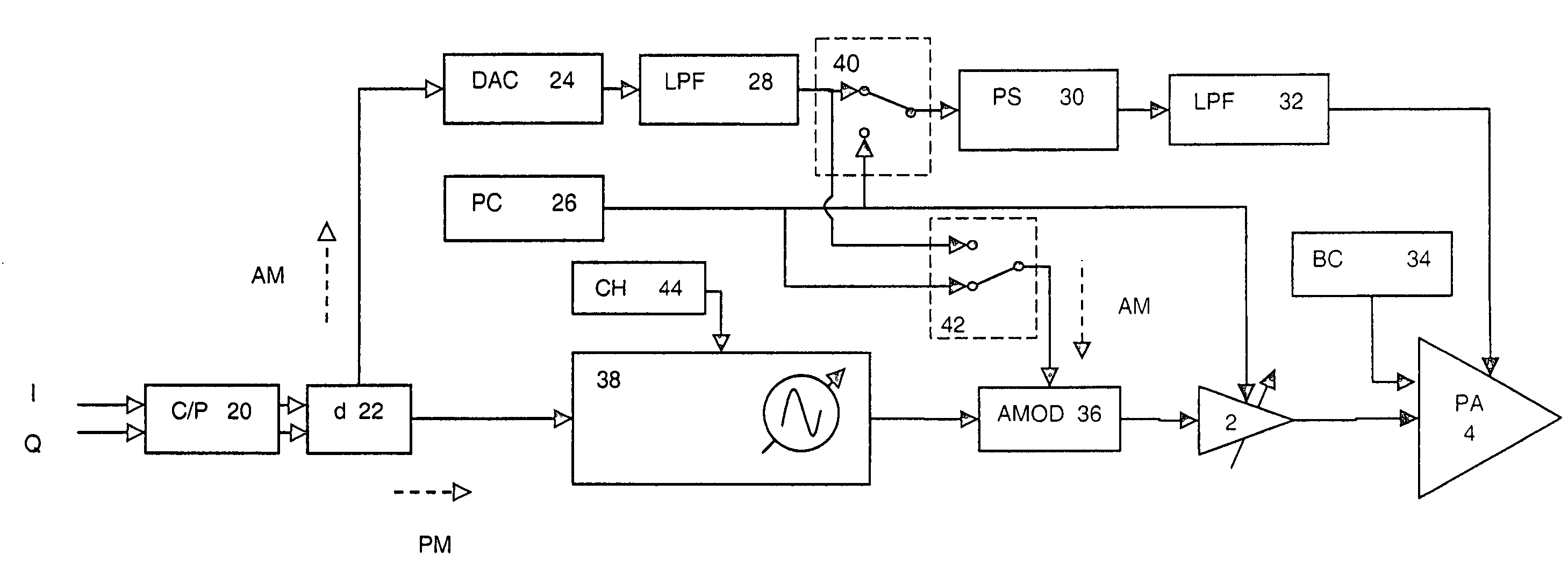
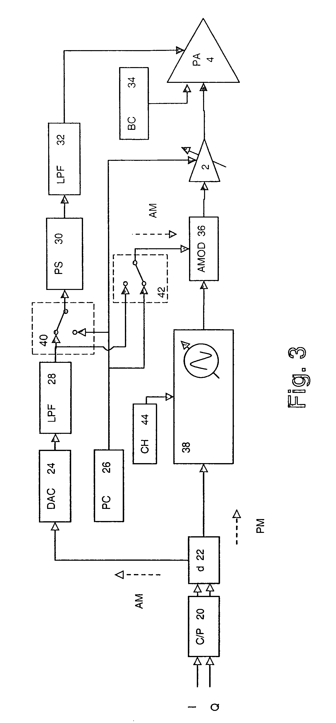
[0038] The embodiment of the present invention will now be described in connection with a reconfigurable polar transmitter as shown in FIGS. 3 and 4 to be used in a cellular radio system. As an example, reconfigurable polar transmitter can be part of a mobile terminal device, such as a mobile phone or mobile computer terminal, or a base station device. The circuitry shown in FIGS. 3 and 4 can be integrated as a single chip or a chip set to be assembled in at least one of the above mentioned mobile terminal device or base station device.

[0039] According to the embodiment, the polar transmitter can be changed between switched-mode operation (switched operation mode) and a linear-mode operation (linear operation mode) as desired, depending on which mode of operation best meets the needs of the radio system in use.

[0040] When operating in switched-mode as shown in FIG. 3, the power supply 30 of a power amplifier 4 is amplitude modulated and the input of the power amplifier 4 is suppli...


PUM


Abstract

A transmission device and method are shown, wherein an amplification is implemented which can be changed between a switched operation mode and linear operation mode as desired, depending on which mode of operation best meets the needs of the radio system in use. This opens the possibility of using the same hardware for different systems.

Description

FIELD OF THE INVENTION [0001] The invention relates to a transmission device and method for use in a transmission system, such as a cellular radio transmission system. BACKGROUND OF THE INVENTION [0002] A power amplifier (PA) is a critical part of any radio transmitter. It amplifies the information-bearing RF (Radio Frequency) signal to a suitable power level for transmission. It is usually the last active section in the transmitter (TX) chain before the antenna. It typically also has the highest power consumption of any single part of the transmitter. [0003] There are many different classes of power amplifiers. They can be distinguished from each other in terms of topology, or in the way in which they are driven or matched. [0004] Most power amplifiers currently used in modern wireless communications are linear. This means that the input signal to the power amplifier is a fully modulated RF signal, containing all amplitude and phase modulation, already applied earlier in the transm...

Claims


Application Information

Patent Timeline
Patent Type & Authority Applications(United States)
IPC IPC(8): H04L27/00H04L25/03H04L25/49H04K1/02
CPCH03F1/0233H03F2200/331H03F1/0277H03F1/0261
Inventor SHAKESHAFT, NIALL ERICJARVINEN, ESKO ANTEROALANEN, MARKO JUHANIGRIGORE, VLAD GABRIELMATERO, JORMA PERTTIKESTI, JARKKO HENRIKKI
Owner NOKIA CORP
Why Eureka
Try Eureka