DNA biochip and methods of use

a biochip and dna technology, applied in the field of dna biochip and methods of use, can solve the problems of immunological assays, children with weaker immune systems are at greater risk, and the success of analysis is extremely difficul

Active Publication Date: 2007-01-18
ALABAMA STATE UNIVERSITY +1
View PDF9 Cites 22 Cited by
  • Summary
  • Abstract
  • Description
  • Claims
  • Application Information

AI Technical Summary

Problems solved by technology

Until recently, electron microscopy was used as the main tool for imaging DNA; however this technique can be harsh on biological samples, making successful analysis extremely difficult.
One of the most challenging aspects in development of these sensors is immobilization and integration of biological molecules in the sensor platform.
Children with weaker immune systems are at greater risk.
Current methods of detection are based on one single technology, i.e., immunological assays and they are very expensive and have low sensitivity and specificity.

Method used


Image

  • DNA biochip and methods of use
  • DNA biochip and methods of use
  • DNA biochip and methods of use

Examples


example 1

Preparation of Porous Silicon Wafer with Immobilized DNA

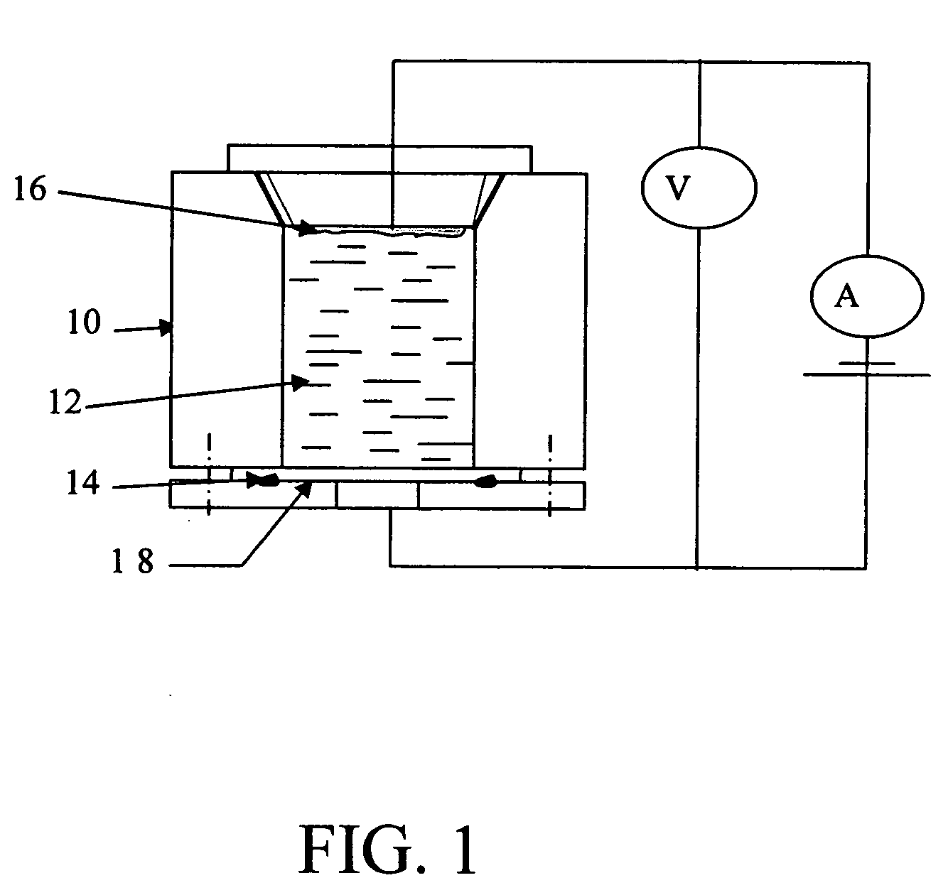
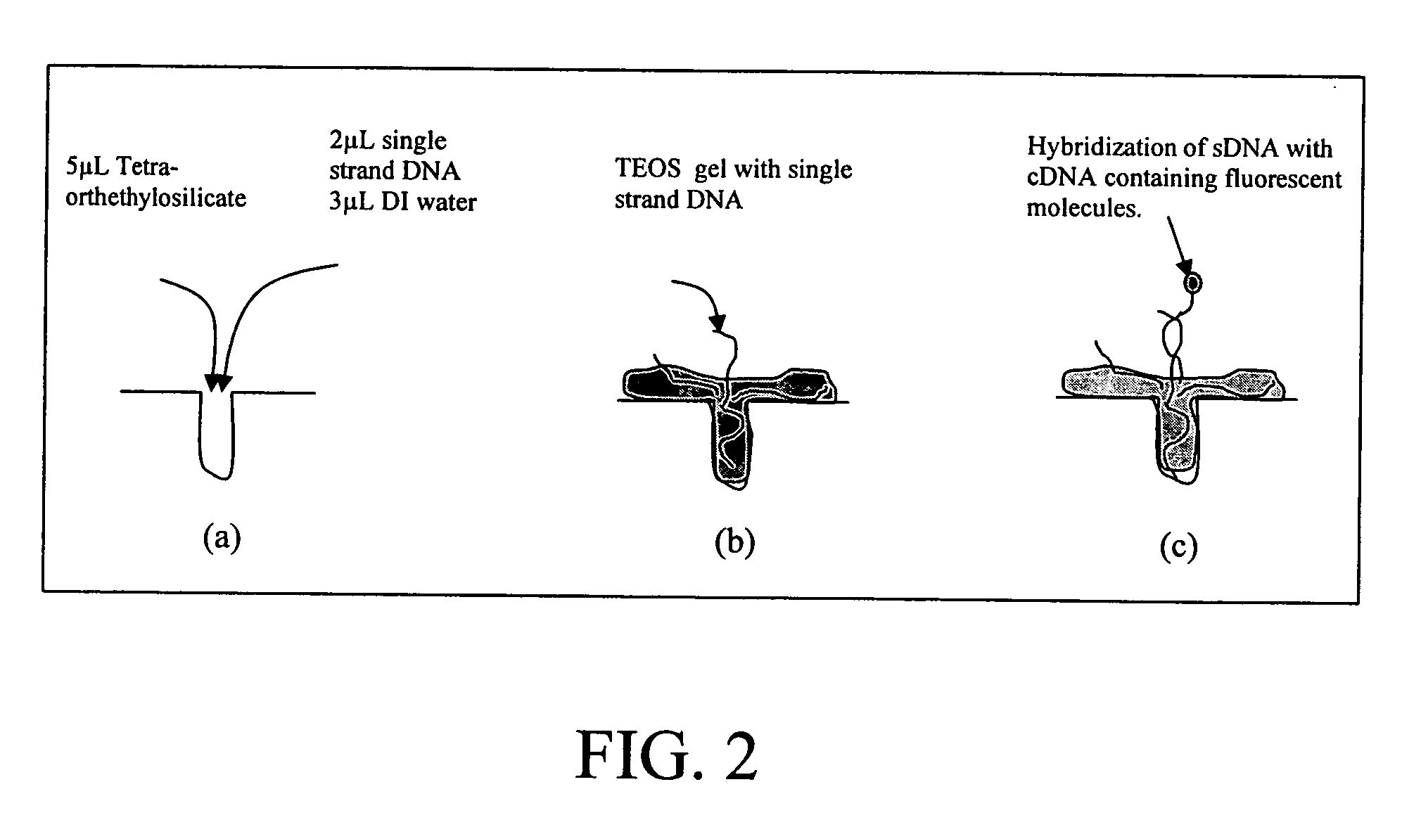
[0052] Porous silicon provides numerous sites for nucleic acid sequence to attach. The porous layer of silicon was fabricated by means of the electrochemical etching in HF solution. FIGS. 4A-4C show the surface of porous silicon after etching. In this case, only a small quantity of charge was generated to generate the pores over the silicon wafer surface. Single strand DNA (sDNA) (SEQ ID NO: 1) of RSV virus was immobilized on PS. A fluorescent probe molecule was attached to a cDNA (SEQ ID NO: 2) having a sequence complementary to the sequence in SEQ ID NO: 1 and then brought into contact with the PS having the sDNA immobilized thereon under conditions sufficient for hybridization of the cDNA to the immobilized sDNA. The fluorescent molecule on the cDNA provides the means of detecting the extent of hybridization of the cDNA to the sDNA.

example 2

SEM Characterization of Microcavities on Silicon Wafer

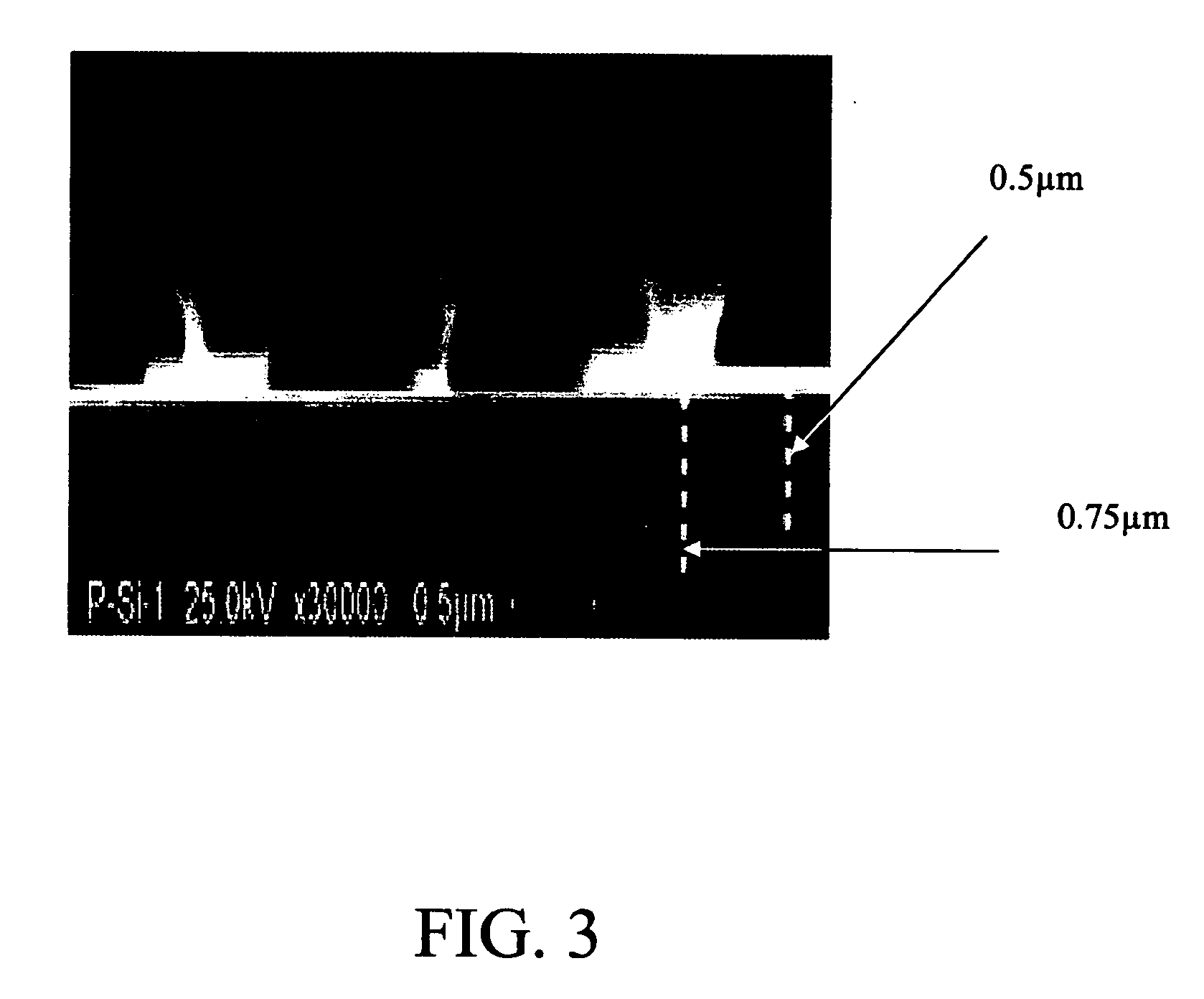
[0053] A cross-section SEM picture of a porous silicon microcavity is shown in FIG. 3. This picture was taken transversally to the silicon surface and illustrates hemispherical structures over the entire surface. These structures represent the beginning stage of porous silicon formation. Furthermore, pore depths varying between 0.5 and 0.75 μm are highlighted in the figure by white-dotted lines.

example 3

Optical Microscopy (EPI) Studies of DNA Biochip

[0054] Epi indicates incident illumination and has been used in the present invention. The reflection and refraction of light according to the multiple wavelet concepts, now known as the Huygens' principle. When the wavefront encounters the interface between the two media, a portion of the light is reflected and another part is refracted. The periodic rows of miniature semicircular red waves represent the Huygens wavelets that together compose the incident and reflected wave fronts. Wavelets that penetrate the media boundary to become refracted are portrayed in blue, as is the line passing through the center of the refracted beam that denotes their direction of propagation. According to the Huygens model of light, a small portion of each angled wavefront impacts the second medium before the rest of the front reaches the interface. This portion of the wavefront begins to move through the second medium while the rest of the wave is still...


PUM

PropertyMeasurementUnit
Tmaaaaaaaaaa
resistivityaaaaaaaaaa

Abstract

The subject invention concerns materials and methods for detecting nucleic acid sequences. One aspect of the invention concerns a silicon-based “biochip” comprising nucleic acid immobilized thereon. In one embodiment, the silicon comprises microcavities. The nucleic acid to be assayed for the presence of one or more target nucleic acid sequences is immobilized on the silicon. A nucleic acid, such as an oligonucleotide probe, having a sequence substantially complementary to the target nucleic acid sequence can be used to detect the immobilized nucleic acid on the silicon. If the nucleic acid used for detection hybridizes with a target nucleic acid sequence, the hybridized sequences can be detected directly or indirectly. In an exemplified embodiment, the oligonucleotide probe can be labeled with a detectable label, for example, a fluorescent molecule. The subject invention also concerns methods for detecting a target nucleic acid using a silicon-based biochip of the invention.

Description

CROSS-REFERENCE TO A RELATED APPLICATION [0001] This application claims the benefit of U.S. Provisional Application Ser. No. 60 / 649,961, filed Feb. 4, 2005, which is hereby incorporated by reference herein in its entirety, including any figures, tables and drawings.BACKGROUND OF THE INVENTION [0002] DNA plays an important role in many cellular processes like replication, homologous recombination and transcription. Besides its genomic information, DNA exhibits very interesting biophysical and physicochemical properties which are essential for proper functioning of the biomolecular processes involved. Biochips, particularly those based on DNA are powerful devices that integrate the specificity and selectivity of biological molecules with electronic control and parallel processing of information. This combination will potentially increase the speed and reliability of biological analysis. Microelectronic technology is especially suited for this purpose since it enables low-temperature p...

Claims


Application Information

Patent Timeline
Patent Type & Authority Applications(United States)
IPC IPC(8): C12Q1/68C12M1/34
CPCG01N33/56983G01N33/5308C12Q1/6837C12Q1/6825C12Q2527/125C12Q2565/501C12Q2565/607
Inventor KUMAR, ARUNKUMAR, ASHOKSINGH, SHREE R.ZEKRI, SOUHEIL
Owner ALABAMA STATE UNIVERSITY
Why Eureka
Try Eureka