Method for generating and displaying examination images and associated ultrasound catheter

a technology of ultrasound catheter and image, which is applied in the field of generating and displaying examination images, can solve the problems of reducing so as to facilitate the registration with the three-dimensional data set of the imaging method, the effect of increasing the accuracy of the examination imag

Inactive Publication Date: 2007-01-18
SIEMENS AG
View PDF9 Cites 57 Cited by
  • Summary
  • Abstract
  • Description
  • Claims
  • Application Information

AI Technical Summary

Benefits of technology

[0010] To further increase the accuracy of the examination images, with the method according to the invention it can be provided that an electrocardiogram of the patient is recorded. This recording of the cardiac cycle enables the ultrasound examination data to be correlated with the electrocardiogram data. In this way each individual image can be assigned the relevant phase position during the cardiac cycle and, on the basis of this data, ultrasound examination data having the same phase position can be displayed. If the displayed examination images have been recorded during the same phase of the cardiac cycle, the display will not be affected by the different blood flow rates in the course of a cardiac cycle.
[0011] According to a further development of the method according to the invention it can be provided that an ultrasound catheter having at least one position sensor is used. The position sensor allows the position of the ultrasound catheter to be determined three-dimensionally so that registration with the three-dimensional data set of the imaging method is facilitated.

Problems solved by technology

However, this method provides no quantitative information in respect of the blood flow rate in the vessels.
The disadvantage of this technique, however, is that the anatomy of the blood vessels under examination is displayed three-dimensionally less precisely and with lower resolution compared to 3D rotational angiography.

Method used


Image

  • Method for generating and displaying examination images and associated ultrasound catheter
  • Method for generating and displaying examination images and associated ultrasound catheter
  • Method for generating and displaying examination images and associated ultrasound catheter

Examples


Embodiment Construction

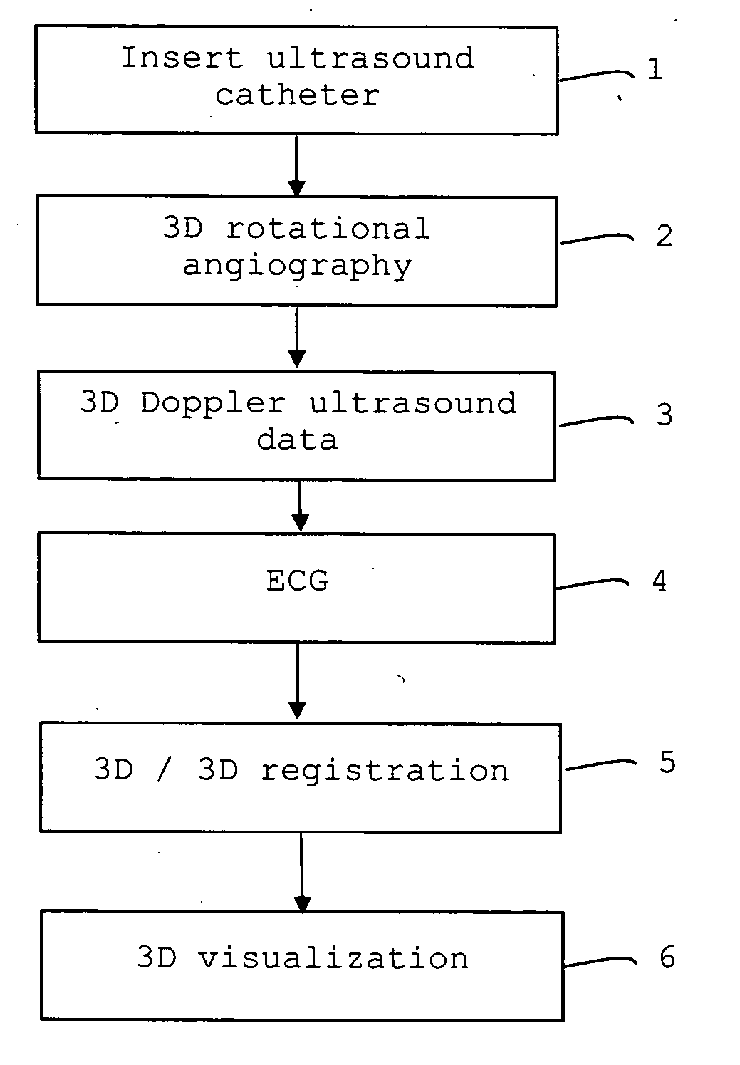
[0021] The flowchart illustrated in FIG. 1 shows the essential steps of the method for generating and displaying examination images of a patient's vessel.

[0022] After the insertion 1 of the ultrasound catheter in the blood vessel to be examined, x-ray projections are recorded by means of 3D rotational angiography 2 as the imaging method. In the case of an aneurysm in the aorta, the ultrasound catheter is positioned in the aorta. For a carotid stenosis, the ultrasound catheter is used in the jugular vein or in an adjacent artery. In the case of an aneurysm or an AVM (arteriovenous malformation) in the brain, the ultrasound catheter is positioned in the brain or in an adjacent artery.

[0023] Doppler ultrasound data 3 is acquired via ultrasound sensors of the ultrasound catheter. Steps 2 and 3, i.e. the performing of 3D rotational angiography and the acquisition of the Doppler ultrasound data 3, take place simultaneously, also consecutively if necessary in the case of other methods. I...


PUM


Abstract

The invention relates to a method for generating and displaying examination images of a vessel of a patient, comprising the following steps: a) acquiring examination data of the vessel using a first imaging method such as computer tomography, magnetic resonance, or angiography, in particular 3D rotational angiography, b) creating a 3D data set on the basis of the acquired examination data of the first imaging method, c) acquiring examination data and the position of an ultrasound catheter inserted into the vessel, d) creating a 3D data set on the basis of the acquired ultrasound catheter examination and position data as a second imaging method, e) registering the 3D data sets of the first and second imaging method, and f) displaying the registered 3D data sets.

Description

CROSS REFERENCE TO RELATED APPLICATIONS [0001] This application claims priority of German application No. 102005022345.1 filed May 13, 2005, which is incorporated by reference herein in its entirety. FIELD OF THE INVENTION [0002] The invention relates to a method for generating and displaying examination images of a vessel of a patient and an ultrasound catheter suitable for carrying out said method. BACKGROUND OF THE INVENTION [0003] Nowadays a whole range of different imaging methods is available, each of which is particularly suitable for a particular examination. For example, 3D rotational angiography is used as an x-ray method for imaging the anatomy of blood vessels and vascular trees. However, this method provides no quantitative information in respect of the blood flow rate in the vessels. [0004] Ultrasound Doppler is used to measure blood flow characteristics such as the blood flow rate, corresponding methods and devices being proposed e.g. in U.S. Pat. No. 5,957,138 and U....

Claims


Application Information

Patent Timeline
Patent Type & Authority Applications(United States)
IPC IPC(8): A61B5/05
CPCA61B5/02007A61B5/0402A61B6/032A61B6/12A61B6/504A61B6/5247A61B8/0808A61B8/12A61B8/13A61B8/4245A61B8/483A61B8/5238A61B6/507A61B8/06A61B8/4254A61B5/318A61B5/33
Inventor CAMUS, ESTELLEKLEEN, MARTINREDEL, THOMAS
Owner SIEMENS AG
Why Eureka
Try Eureka