
Apparatus and method for dispensing frozen carbonated beverages

a technology for carbonated beverages and apparatuses, applied in lighting and heating apparatus, ice production, refrigeration machines, etc., can solve the problems of large floor space and bulky apparatuses, and achieve the effect of enhancing the carbonation process

Inactive Publication Date: 2007-01-25
IMI CORNELIUS
View PDF10 Cites 19 Cited by
  • Summary
  • Abstract
  • Description
  • Claims
  • Application Information

AI Technical Summary

Benefits of technology

[0007] The pressure in the freeze chamber is related to the level (volume) of frozen carbonated beverage in the freeze cylinder and controlling the addition of unfrozen beverage to the freeze chamber in response to the pressure provides a simple and effective method of controlling the beverage level in the freeze chamber.
[0009] Preferably, beverage is added to the freeze cylinder at a rate that matches the cooling rate of the beverage within the freeze cylinder so that unfrozen beverage added to the freeze chamber is rapidly frozen and does not significantly alter the viscosity (consistency) of the frozen carbonated beverage within the freeze cylinder. In this way, frozen carbonated beverage having the desired viscosity (consistency) may be dispensed while adding unfrozen beverage to the freeze chamber.
[0018] Carbonating the beverage in the freeze chamber avoids the provision of a separate carbonator to carbonate the beverage.
[0025] By matching the fill rate to the cooling rate, unfrozen beverage added to the freeze chamber is converted to frozen beverage in an efficient manner and does not significantly affect the viscosity (consistency / quality) of the frozen beverage in the freeze chamber.
[0028] By adding the beverage and carbonating gas to the freeze chamber in the same line, carbonation of the beverage within the freeze chamber is promoted so that the desired carbonation level can be achieved and carbonated beverage frozen in an efficient manner. Some pre-carbonation of the beverage in the supply line may also be effected thereby further enhancing the carbonation process.

Problems solved by technology

Such apparatus can be bulky and require a large amount of floor space.

Method used


Image

  • Apparatus and method for dispensing frozen carbonated beverages
  • Apparatus and method for dispensing frozen carbonated beverages

Examples


Embodiment Construction

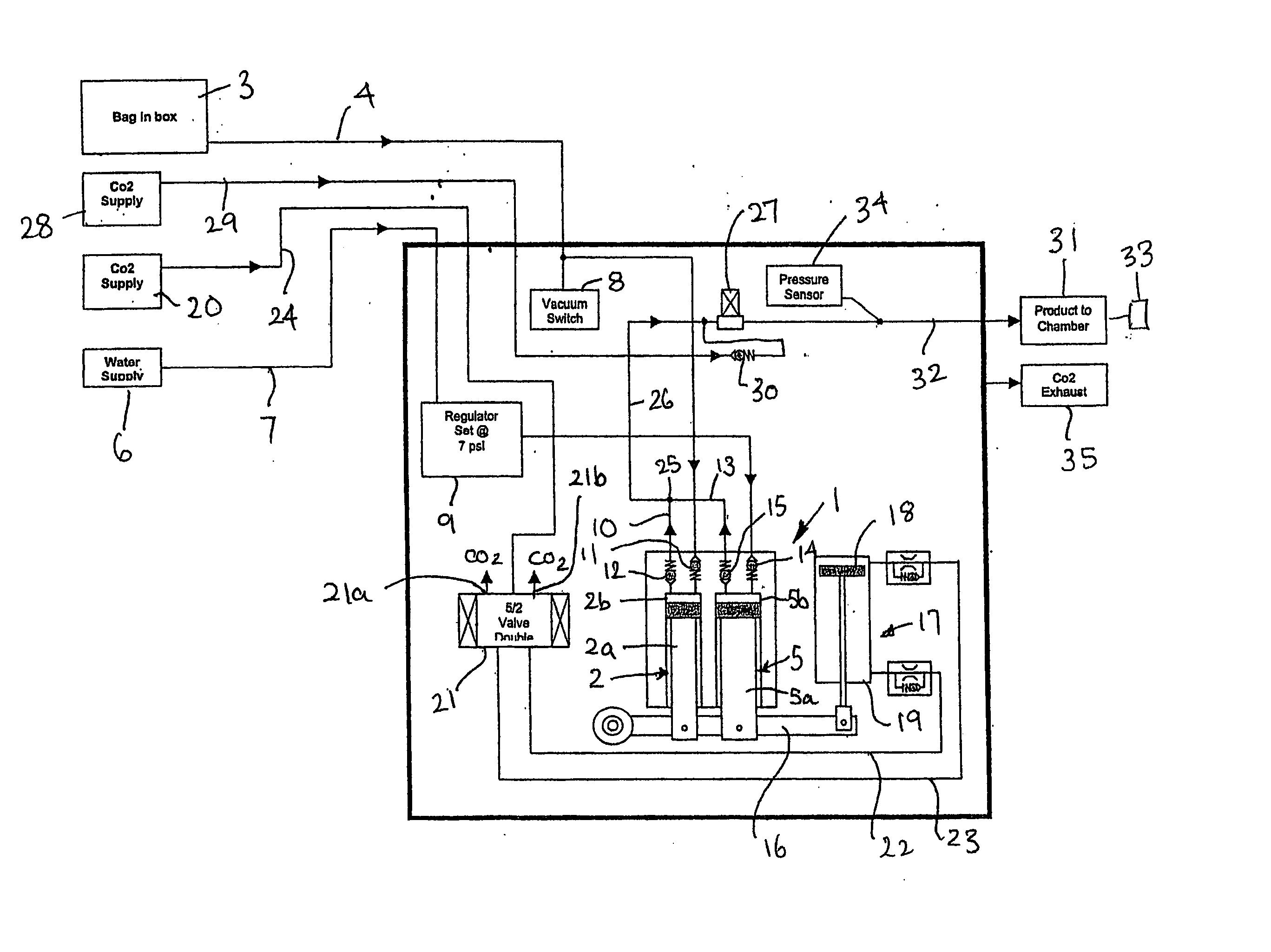
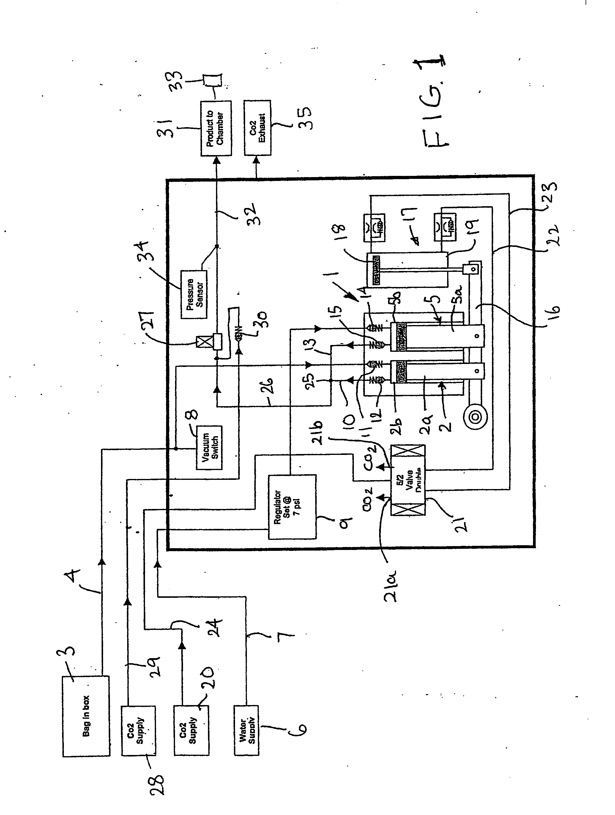
[0032] The invention will now be described in more detail, by way of example only, with reference to the accompanying FIG. 1 schematic drawing of one embodiment of an apparatus for dispensing frozen carbonated beverages according to the invention.

[0033] As shown the apparatus has a ratio pump 1 having a syrup pump unit 2 connected to a source 3 of syrup via a syrup line 4 and a water pump unit 5 connected to a source 6 of water via a water line 7. In this embodiment the source 3 of syrup is a so-called “bag in box” container and the source 6 of water is the mains supply. It will be understood however that any other suitable sources of syrup and water may be employed.

[0034] A vacuum switch 8 is provided in the syrup line 4 to detect when the syrup source 3 is empty and provide a signal to an electronic control unit (not shown), for example a printed circuit board, to shut-down the ratio pump 1 until the syrup source 3 is replaced. A visual and / or audible warning signal may be provi...


PUM


Abstract

Frozen carbonated beverage apparatus and method is illustrated, and has a freeze chamber in which beverage is frozen wherein the addition of beverage to the freeze chamber is controlled in response to pressure in the freeze chamber. Controlling the addition of unfrozen beverage to the freeze chamber in response to the pressure provides a method of controlling the beverage in the freeze chamber. As freeze chamber pressure falls to a pre-determined lower pressure, beverage is added to the freeze chamber until a pre-determined upper pressure. Beverage may be added to the freeze cylinder at a rate that matches the cooling rate of the beverage within the freeze chamber so that unfrozen beverage added to the freeze chamber is rapidly frozen and does not significantly alter the viscosity (consistency) of the frozen carbonated beverage.

Description

[0001] This invention relates to an apparatus and method for, dispensing a frozen carbonated beverage. BACKGROUND OF THE INVENTION [0002] The invention has application to dispense of both alcoholic and nonalcoholic frozen carbonated beverages. For convenience, the invention is described hereinafter with reference to dispense of frozen carbonated beverages formed by a combination of carbonated water and a syrup. It will be understood however that the invention is not limited to such application and dispense of other types of beverages is included within the scope of the invention. [0003] Apparatus for producing frozen carbonated beverages from the partial freezing of a combination of carbonated water and syrup to produce a so-called “slush” beverage is well known, see for example U.S. Pat. Nos. 3,608,779 and 3,460,713. As used herein, the term “frozen” is used to describe beverages of this type and includes terms such as “semi-frozen”. [0004] There are many types of apparatus for pro...

Claims


Application Information

Patent Timeline
IPC IPC(8): F25C1/00A23G9/04A23G9/28
CPCA23G9/28A23G9/045F25B9/008
Inventor MOULDER, STEVENWHITTINGTON, IAN THOMAS RICHARDDAVIS, TERRENCE ROBERT
Owner IMI CORNELIUS
Learn More