Photocatalyst water treating apparatus

a photocatalytic water and water treatment technology, applied in chemical/physical/physical-chemical processes, chemical/physical processes, water treatment nature, etc., can solve the problems of clogging of piping, serious problems, and all conventional photocatalytic water-processing technologies face the same problems

Inactive Publication Date: 2007-01-25
REIKEN
View PDF2 Cites 19 Cited by
  • Summary
  • Abstract
  • Description
  • Claims
  • Application Information

AI Technical Summary

Benefits of technology

[0014] An object of the present invention is to provide a photocatalytic water-processing system that allows unprecedented water-processing in which rust deposits and scale of silica, magnesium and other inorganic compounds formed in the reservoir of the system, in which to store water that requires processing (e.g., industrial circulating water), or in the piping, or over the UV-lamp jacket of the system, are dissolved and removed without using any chemicals.

Problems solved by technology

On the other hand, clogging of the piping caused by scale deposits of inorganic compounds and metal corrosion has posed a serious problem, and there has been a great need in various industries for the development of new water-processing technologies to decompose and remove these materials.
All of the conventional photocatalytic water-processing technologies face the same problem, however.
A long term use of the system results in the deposition of scale and oil on the silica glass jacket of the UV-lamp, decreasing the UV transmittance.
The resulting decrease in the UV-lamp performance makes the long-term, stable processing of water difficult.
However, chemicals used in this type of water-processing system to decompose and remove COD and BOD components, hexane extracts, total phosphorus, and total nitrogen present in waste water requires a reaction tank for processing.
In addition, the running cost of this system is high.

Method used


Image

  • Photocatalyst water treating apparatus
  • Photocatalyst water treating apparatus
  • Photocatalyst water treating apparatus

Examples


examples

[0101] The present invention will now be described with reference to an exemplary experiment, which is not intended to limit the scope of the invention in any way.

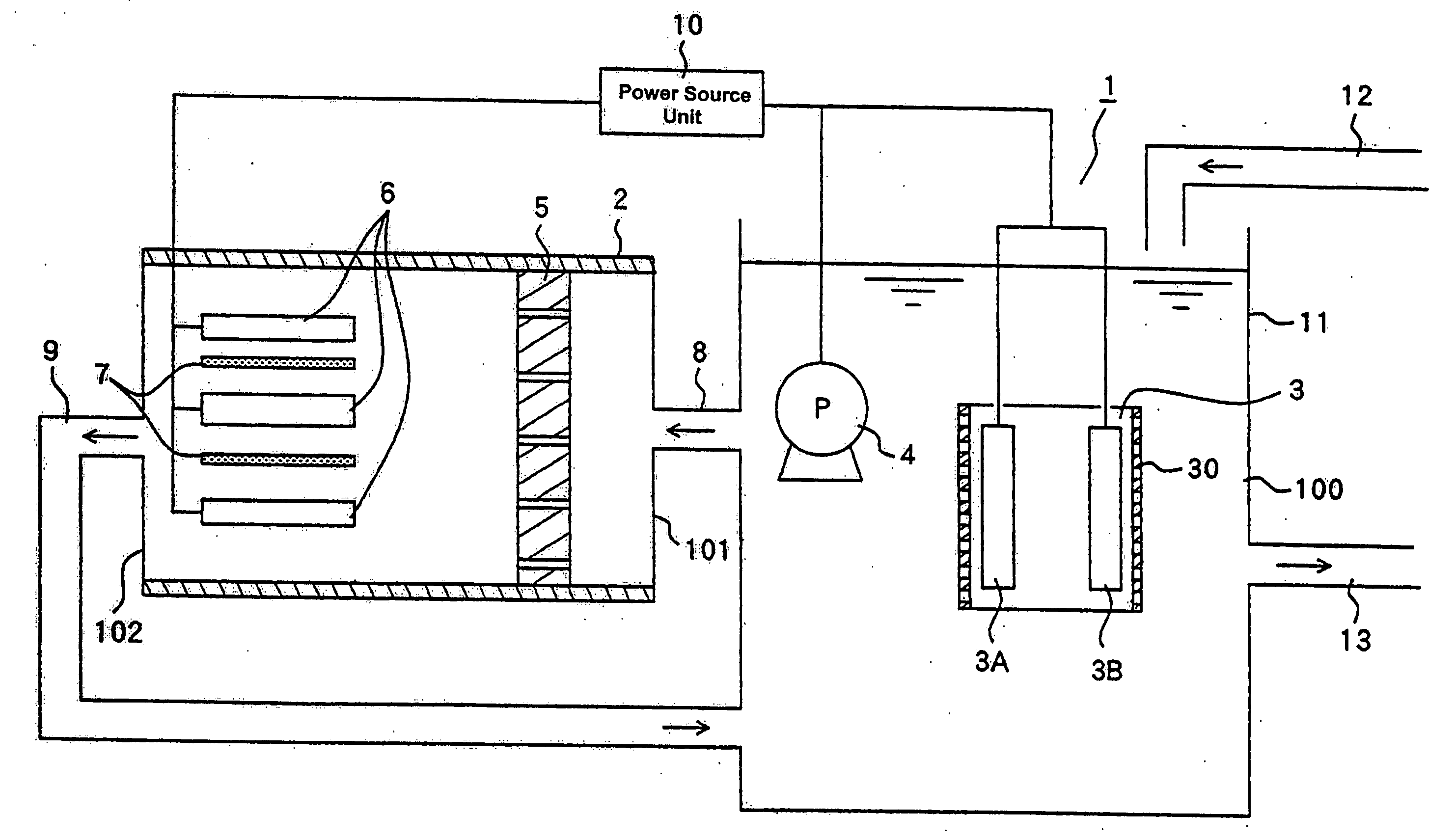
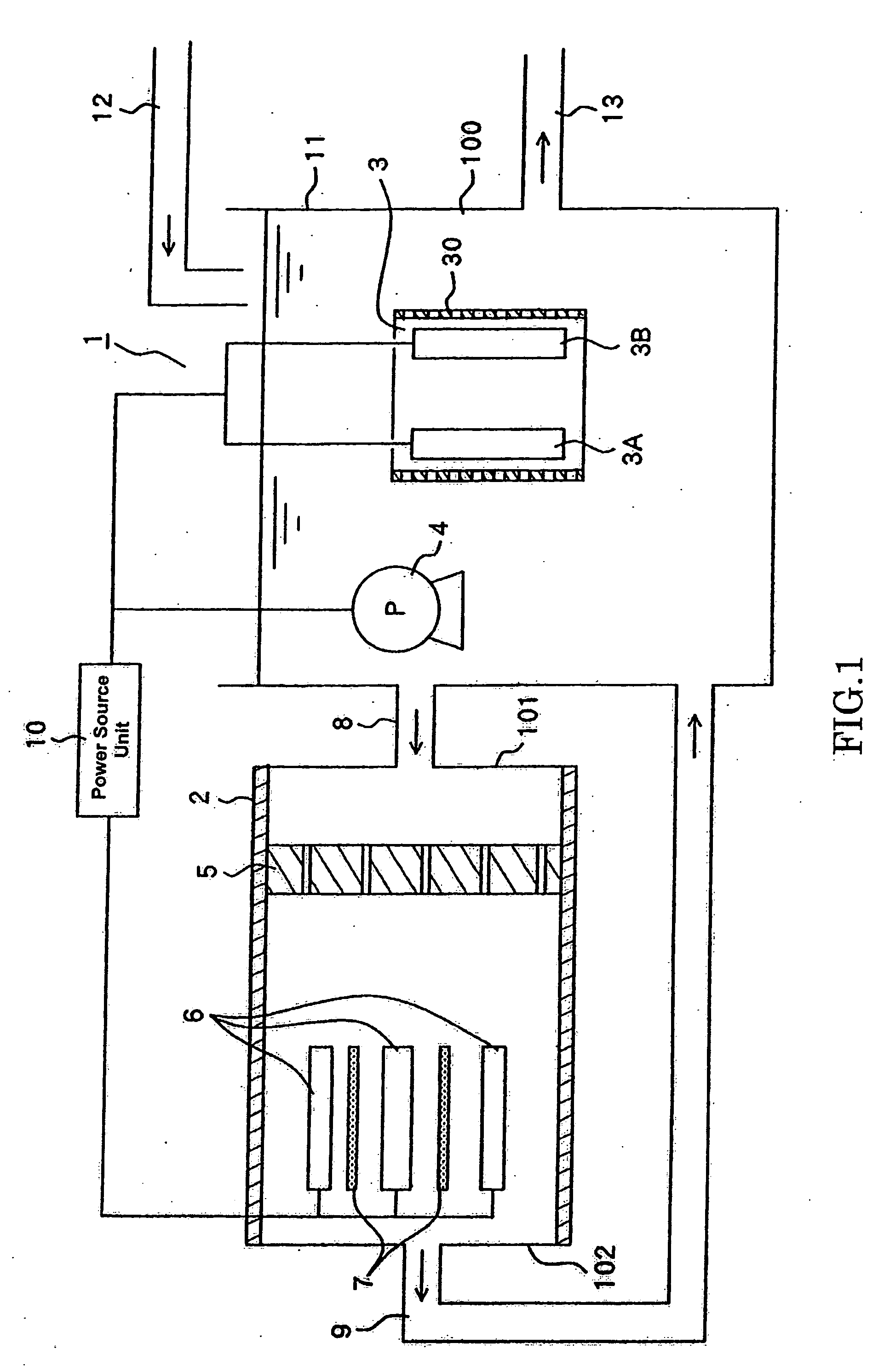
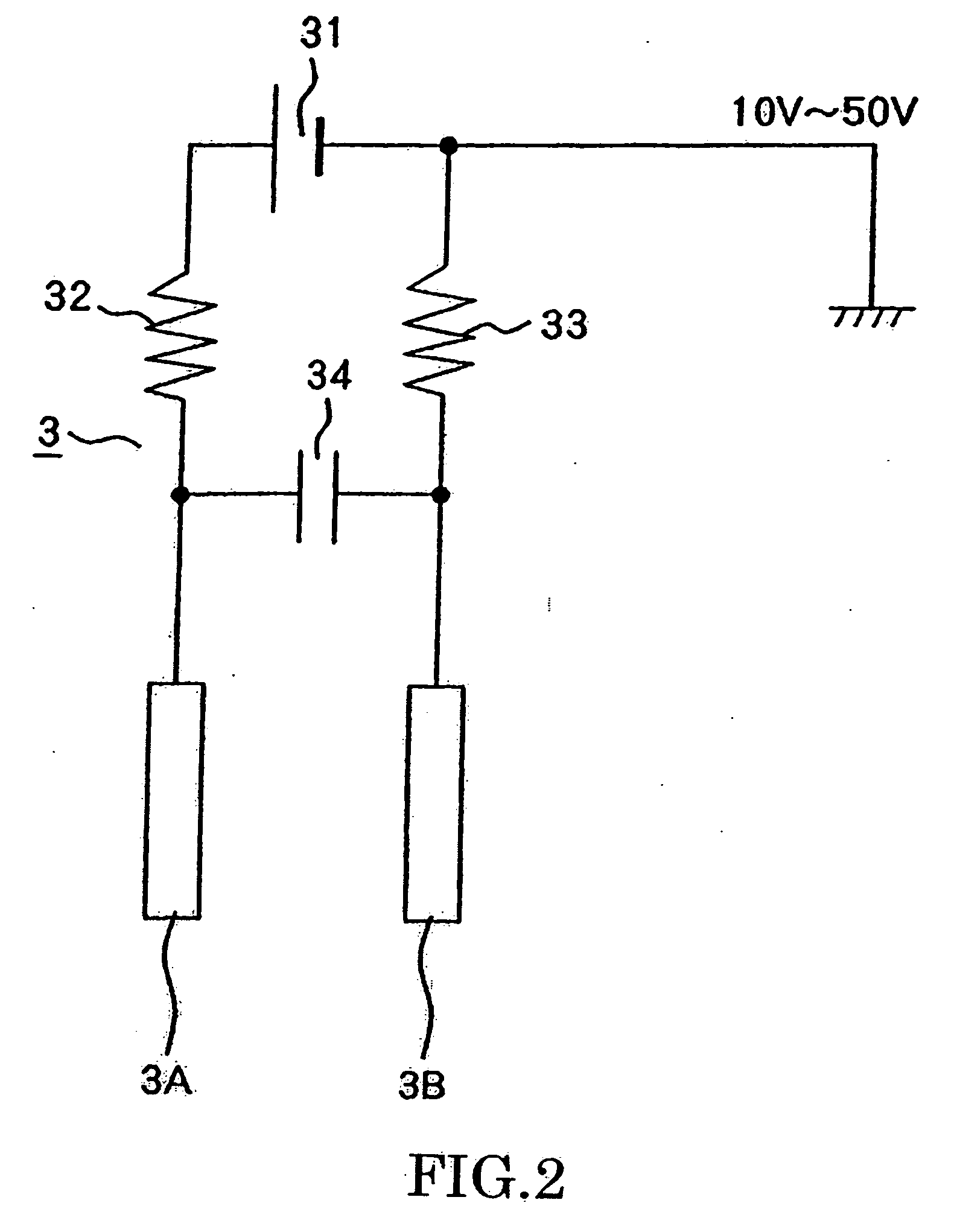
[0102] In this experiment, the water 100 to be processed is industrial circulation water (tap water) and the reservoir 11 used was a 10-ton open cooling tower. The water temperature in the cooling tower was 25° C. during water processing. The electrodes 3A and 3B of the electrode unit 3 were each a 4 cm×20 cm platinum-plated expanded titanium alloy plate. A 16V DC voltage was applied to the electrodes 3A and 3B for the water processing. The pump 4 was an inverter-controlled 0.75 kw pump manufactured by Hitachi, Ltd. The filter 5 was a 140-mesh polypropylene fabric. Two 14W low-pressure mercury lamps that emit radiation with a wavelength of 254 nm were used as the UV-lamps 6. The photocatalyst carriers 7 were each an expanded titanium dioxide piece.

[0103] In this experiment, a photocatalytic water-processing system 1 havi...


PUM

PropertyMeasurementUnit
output voltageaaaaaaaaaa
voltageaaaaaaaaaa
oxidation-reduction potentialaaaaaaaaaa

Abstract

An object is to dissolve and remove rust and scale deposits of inorganic compounds formed in a reservoir, in which to store water that requires processing, or in piping, or on a jacket of a UV-lamp without using any chemicals. A photocatalytic water-processing system utilizes a reservoir 11 in which organic and inorganic materials present in water 100 that requires processing the water are decomposed. The system comprises: a circulation path including: a main unit 2 arranged outside the reservoir 11; an inlet pipe 8 connecting to an inlet of the main unit 2; and an outlet pipe 9 connecting to an outlet of the main unit 2; a pump 4 for circulating the water; a filter 5 arranged within the main unit 2; photocatalytic processing means arranged downstream of the filter 5 and including a photocatalyst carrier 7 and a UV-lamp 6; and an electrode unit 3 arranged within the reservoir 11. The water 100 is electrolyzed as a current is applied to the electrode unit 3.

Description

TECHNICAL FIELD [0001] The present invention relates to a photocatalytic water-processing system that utilizes a reservoir where water that requires processing, such as industrial circulating water, is temporarily stored and inorganic materials present in the water are decomposed by electrolysis. In particular, the present invention relates to a photocatalytic water-processing system in which rust deposits and scale of silica, magnesium and other inorganic compounds formed in the reservoir or the piping or over the UV-lamp of the system are decomposed and removed by electrolysis without using any chemicals. BACKGROUND ART [0002] Criteria for the maintenance and improvement of water quality have been seriously reviewed recently, and there is an increasing need for more sophisticated water-processing technologies that ensure sufficient water quality. In particular, development of water-processing technologies for removing environmental hormones, such as dioxin, organochlorine compound...

Claims


Application Information

Patent Timeline
Patent Type & Authority Applications(United States)
IPC IPC(8): B01J19/12B01D39/06B01D39/16B01D39/20B01J35/02C02F1/28C02F1/30C02F1/32C02F1/46C02F1/461C02F1/467C02F1/72C02F5/00
CPCC02F1/001C02F2305/10C02F1/325C02F1/461C02F1/46109C02F1/4618C02F1/4674C02F1/725C02F2001/46142C02F2101/10C02F2101/30C02F2103/023C02F2103/42C02F2201/3227C02F2201/324C02F2201/4617C02F1/283
Inventor KURAMOTO, HIKARUHASHIMOTO, SHIGEKI
Owner REIKEN
Why Eureka
Try Eureka