
Optical disk and manufacturing method therefor

a technology of optical disks and manufacturing methods, applied in the field of optical disks, can solve the problems of difficult to impart the glossiness of receptive layer surfaces, inability to save printed images, etc., and achieve the effect of adequate roughness

Inactive Publication Date: 2007-01-25
HITACHT MAXELL LTD
View PDF2 Cites 2 Cited by
  • Summary
  • Abstract
  • Description
  • Claims
  • Application Information

AI Technical Summary

Benefits of technology

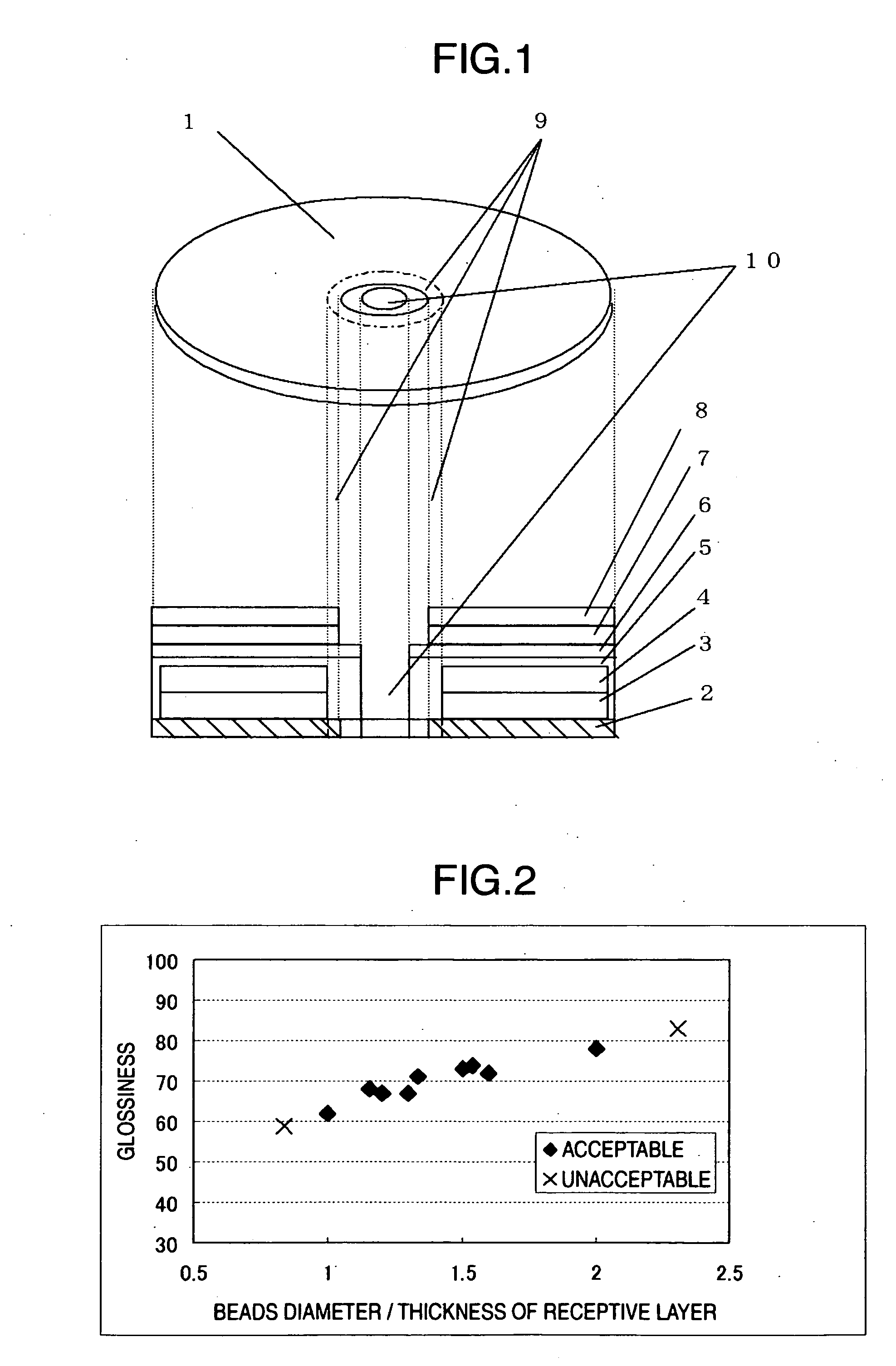
[0012] According to a first aspect of the present invention, there is provided an optical disk comprising a recording layer, a reflective layer, an underlayer and a receptive layer with glossiness capable of receiving print provided on a substrate in this order, wherein the underlayer and the receptive layer among them cover a part up to a clamp area, and the receptive layer at least in the clamp area has acrylic beads having an average particle diameter equal to or larger than the thickness of the receptive layer but twice or less of the thickness of the receptive layer, and the acrylic beads uniformly distributed. The acrylic beads can adequately roughen the surface of the receptive layer, reduces the sticking of the receptive layer to the clamp part of a drive and can prevent the receptive layer from being peeled off, by having a certain size, that is, having the average particle diameter equal to or larger than the thickness of the receptive layer but twice or less.
[0014] A third aspect according to the present invention provides an optical disk comprising a receptive layer with glossiness capable of receiving print prepared on a side of a substrate opposite to the light-incoming side of the optical disk, and an underlayer between the substrate and the receptive layer, wherein the underlayer and the receptive layer among them cover a part up to a clamp area, and the receptive layer at least in the clamp area has acrylic beads having an average particle diameter equal to or larger than the thickness of the receptive layer but twice or less of the thickness of the receptive layer, and the acrylic beads uniformly distributed. As in a first aspect according to the present invention, the acrylic beads can adequately roughen the surface of the receptive layer, reduces the sticking of the receptive layer to the clamp part of a drive and can prevent the receptive layer from being peeled off, by having a certain size, that is, having an average particle diameter equal to or larger than the thickness of the receptive layer but twice it or less.
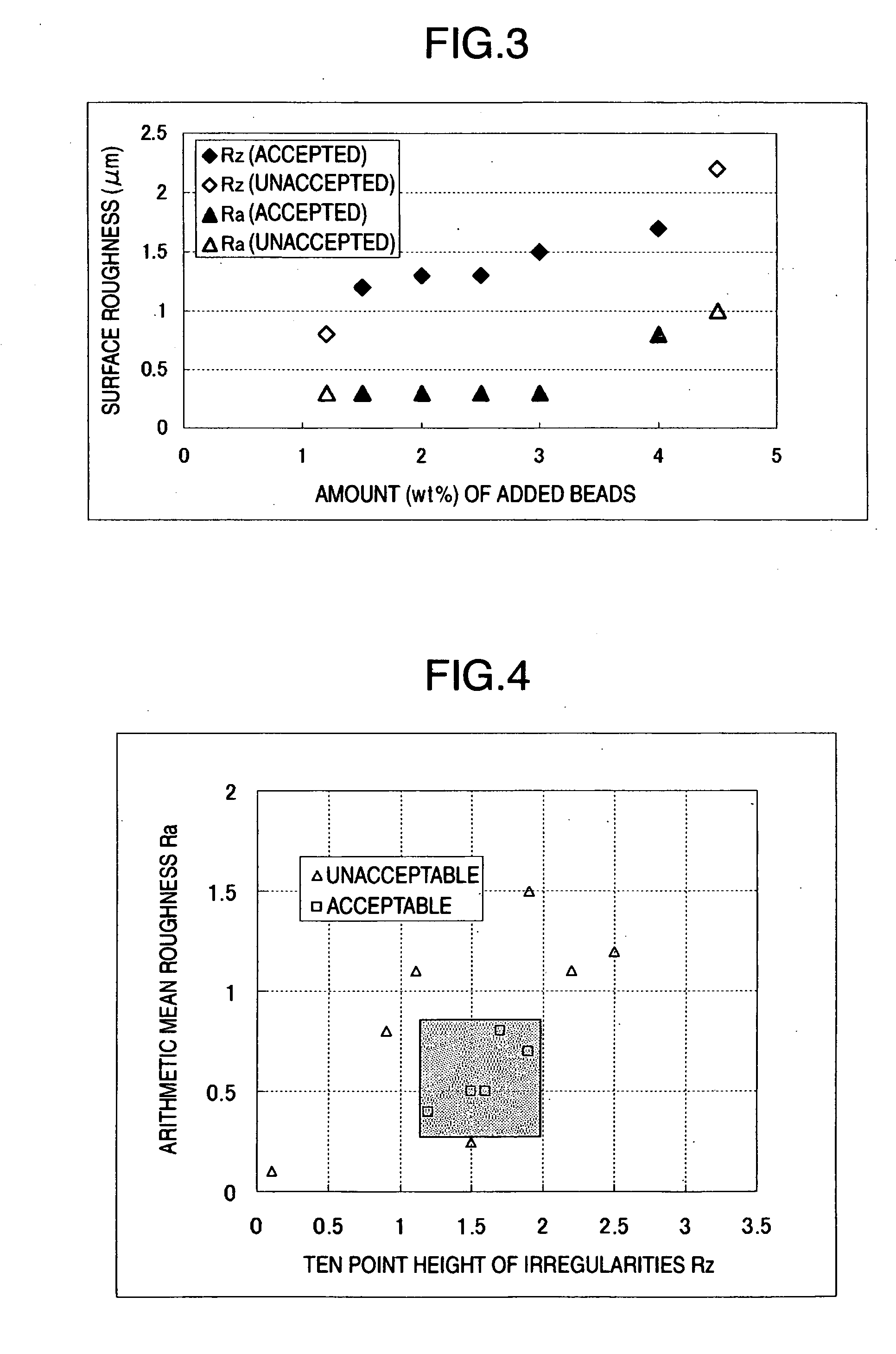
[0018] A seventh aspect according to the present invention provides an optical disk in which the surface of the clamp area further has a ten point height of irregularities of 1.2 μm or more but 2.0 μm or less, and an arithmetic mean roughness of 0.3 μm or more but 0.8 μm or less. The receptive layer does not stick to a chucking mechanism through containing acrylic beads and controlling the surface roughness to 1.2 μm or more but 2.0 μm or less, and can keep glossiness through controlling the arithmetic mean roughness to 0.3 μm or more but 0.8 μm or less.
[0020] A ninth aspect of the present invention provides a method for manufacturing an optical disk, the method comprising the steps of: applying a resin solution containing transparent resin beads; and curing the resin solution to form a receptive layer containing transparent resin beads therein. The method can easily form the receptive layer having an objective function, by applying the resin solution containing the transparent resin beads, and curing the resin solution.
[0023] By adding the acrylic beads as described above into the receptive layer, there can be attained an optical disk wherein adequate roughness is imparted to the surface of the receptive layer, sticking to a chucking mechanism of a drive is prevented, and the receptive layer has glossiness.

Problems solved by technology

However, it has been found that the optical disk having a conventionally used receptive layer provided with glossiness prepared over a clamp area up to the internal circumference part around a center hole causes the sticking of the receptive layer to a chucking mechanism of a drive and cannot be taken out, or causes the peeling of the receptive layer in the clamp area, while being repeatedly inserted into and ejected from a recording and reproducing unit, and consequently cannot save the printed image.
However, when having large surface roughness, the receptive layer generally has low glossiness; and in addition, SiO2 causes scattered reflection due to fine roughness between particles and on the surface of the receptive layer, and a protein powder does not have optical transparency, so that it is difficult for them to impart the receptive layer glossiness.

Method used


Image

  • Optical disk and manufacturing method therefor
  • Optical disk and manufacturing method therefor

Examples


example 1

Relationship Between Bead Diameter and Thickness of Receptive Layer

(Sample A)

[0046] A recording layer 3 with the thickness of 150 nm was formed on a signal surface of a transparent substrate 2 with the thickness of 0.6 mm made from polycarbonate by spin-coating a coloring matter dissolved in tetrafluoropropanol. A reflective layer 4 made from a silver alloy was layered thereon by sputtering.

[0047] The surface of the reflective film 4 was spin-coated with an ultraviolet-curing adhesive, a dummy substrate with the same shape as the discoid transparent substrate 2 made from polycarbonate was laminated thereon, and then the adhesive was cured by being irradiated with an ultraviolet light of a high-pressure mercury lamp from a dummy substrate side.

[0048] Subsequently, a white underlayer 7 was formed on the surface of a region between a radius of 10 mm and a radius of 59 mm in the dummy substrate 6, by fixing a white UV link with a screen printing method and irradiating it with ultra...

example 2

Relationship Between Amount of Added Transparent Resin Beads and Surface Roughness

(Sample J)

[0068] An optical disk was prepared with the same method as in the case of Sample A, except that a conditioned ink containing 1.5 wt % acrylic beads with the average particle diameter of 15 μm for a receptive layer was applied on an underlayer so as to form a film with the thickness of 13 μm.

(Sample K)

[0069] An optical disk was prepared with the same method as in the case of Sample A, except that a conditioned ink containing 1.2 wt % acrylic beads with the average particle diameter of 15 μm for a receptive layer was applied on an underlayer so as to form a film with the thickness of 13 μm.

(Sample d)

[0070] An optical disk was prepared with the same method as in the case of Sample A, except that a conditioned ink containing 4.5 wt % acrylic beads with the average particle diameter of 15 μm for a receptive layer was applied on an underlayer so as to form a film with the thickness of 13 ...

example 3

Relationship Between Arithmetic Mean Roughness Ra and Ten Point Height of Irregularities Rz

(Sample C)

[0071] An optical disk was prepared with the same method as in the case of Sample A, except that a conditioned ink containing 2.5 wt % acrylic beads with the average particle diameter of 15 μm for a receptive layer was applied on an underlayer so as to form a film with the thickness of 13 μm.

(Sample N)

[0072] An optical disk was prepared with the same method as in the case of Sample A, except that a conditioned ink containing 4 wt % acrylic beads with the

[0073] An optical disk was prepared with the same method as in the case of Sample A, except that a conditioned ink containing 2 wt % acrylic beads with the average particle diameter of 15 μm for a receptive layer was applied on an underlayer so as to form a film with the thickness of 13 μm.

(Sample L)

[0074] An optical disk was prepared with the same method as in the case of Sample A, except that a conditioned ink containing 2...


PUM

PropertyMeasurementUnit
arithmetic mean roughnessaaaaaaaaaa
heightaaaaaaaaaa

Abstract

The surface layer of a receptive layer has a water-absorbing property, and when the surface layer of the receptive layer is glossy and a layer to be printed covers up to a clamp area, the medium has a high possibility of causing a sticking of the receptive layer to a chucking mechanism in a drive. For this reason, an optical disk has been demanded which does not cause the peeling of the receptive layer in the clamp area while being used as the medium, provides a clear printed image, and copes with a high-resolution wide printing. In order to make the surface of the receptive layer not stick to the chucking mechanism of the drive, it is necessary to roughen the surface, but when a colored fine particle is contained in the receptive layer, a printed image on the receptive layer becomes unclear. Then, it was found that it is effective to add acrylic beads with an average particle diameter of ½ or larger of the thickness of the receptive layer into the receptive layer, in order to improve the adhesiveness of the beads to a particle absorbent and a macromolecule absorbent used in the receptive layer, reinforce the receptive layer, and realize a clear printed image.

Description

BACKGROUND OF THE INVENTION [0001] The present invention relates to an optical disk on the surface of which an image can be printed, and further specifically relates to the optical disk on the surface of which a photograph-quality image having glossiness can be printed. [0002] In the field of a practically used recordable optical disks such as CD-R and DVD-R, there is an optical disks of a type having a region to be printed thereon formed on the side opposite to the light-incoming side of the optical disk, through providing an ink-receptive layer, so that a user can easily print a title or a content of data recorded in the optical disk on the surface, by use of an ink jet printer for home use. [0003] These optical disks have a clamp area for fixing and rotationally driving the optical disk provided around a disk center hole in a recording and reproducing unit, so that when an image such as a photograph taken with a digital camera is printed on a region to be printed, one part of the...

Claims


Application Information

Patent Timeline
Patent Type & Authority Applications(United States)
IPC IPC(8): B41M5/035G11B7/24053G11B7/24094G11B7/24097
CPCG11B7/24094G11B7/24053
Inventor HOMMA, RYUTANAGANO, HIDEKIMATSUKI, YOTAOBARA, HIROSHIDOI, HIDEKARU
Owner HITACHT MAXELL LTD
Learn More