Method for monitoring combustion stability of an internal combustion engine

a technology of internal combustion engine and stability monitoring, which is applied in the direction of electrical control, process and machine control, instruments, etc., can solve the problems of high nosub>x/sub>, high nosub>x/sub>, particulate emissions, and thermal loss, so as to reduce the number of misfirings due to unstable combustion, the effect of lowering the burnt gas mass fraction and increasing the temperature of the intake air charg

Active Publication Date: 2007-01-25
FORD GLOBAL TECH LLC
View PDF4 Cites 14 Cited by
  • Summary
  • Abstract
  • Description
  • Claims
  • Application Information

AI Technical Summary

Benefits of technology

[0052] It is preferred to lower the burnt gas mass fraction gradually in order to be sure that an extensive response stabilises the combustion within one step only and in the expectation that one change is sufficient for combustion stabilization. Thereby the number of misfirings due to an unstable combustion can be lowered.
[0053] A preferred embodiment of the method is characterized in that intake air charge temperature intake is increased if combustion is not stable. This procedure makes use of the effect described in the introduction, in particular of the effect that combustion can be influenced by changing the charge temperature. By increasing the temperature intake combustion is stabilized because ignition tends to advance due to the fact that in the cylinder charges the conditions for auto-ignition, in particular the ignition-temperature, are reached faster rather than when temperatures are low. Intake air charge temperature intake also can be increased by bypassing an intercooler if provided. A heat exchanger can also be used to increase the charge temperature. If possible an increase of the compression ratio can be used to generate higher cylinder charge temperatures during compression in order to stabilize the combustion.

Problems solved by technology

Another reason for the mentioned higher efficiency of diesel engines is caused by the fact that engine load is controlled by fuel quantity and not by a throttle resulting in thermodynamic losses, in particular during the gas exchange.
However, diesel engines produce higher NOx— and particulate emissions.
Due to the mixing controlled nature of diesel combustion a more or less large fraction of the injected fuel is not sufficiently mixed with the combustion air resulting in an inhomogeneous charge which is in some areas rich, thus leading to particulate emissions.
The combustion starts by auto-ignition when the mixture reaches a certain temperature, namely in charge areas where the air / fuel ratio is nearly stoichiometric resulting in high process temperatures.
The limitations of HCCI—engines relate to controlling the ignition timing and the combustion rate at different operating conditions.
The thermal efficiency may also decrease due to the early heat release before TDC, and the engine becomes rough due to fast and early combustion.
When the engine load decreases, the ignition tends to be retarded which may eventually result in misfiring al well as an increase in HC and CO emissions.
When the engine speed increases, the time for the main heat release tends to be retarded since the time available for low temperature preliminary reaction of the diluted mixture becomes insufficient and misfiring may occur.
One problem to be solved is to prevent the start of combustion while fuel is injected.
Unstable combustion is assumed when stab is greater than 0.05 or in other words: if the standard deviation amounts to 5% or more of the mean value it is expected that such extensive changes in indicated mean effective pressure are caused by combustion stability problems.
However, this procedure is impractical for online calculation because it involves statistics, i.e., data which must be acquired and stored over many cycles.
Moreover, the bookkeeping for this statistics is relatively cumbersome.
Several intermediate variables need to be stored and re-initialized each time the calculations need to be abandoned because the engine operation is not sufficiently steady.
However, if the incrementing or decrementing value Δintake, Δeng and / or ΔFi is chosen small enough, the error introduced by transient operation is negligible.

Method used


Image

  • Method for monitoring combustion stability of an internal combustion engine
  • Method for monitoring combustion stability of an internal combustion engine
  • Method for monitoring combustion stability of an internal combustion engine

Examples


first embodiment

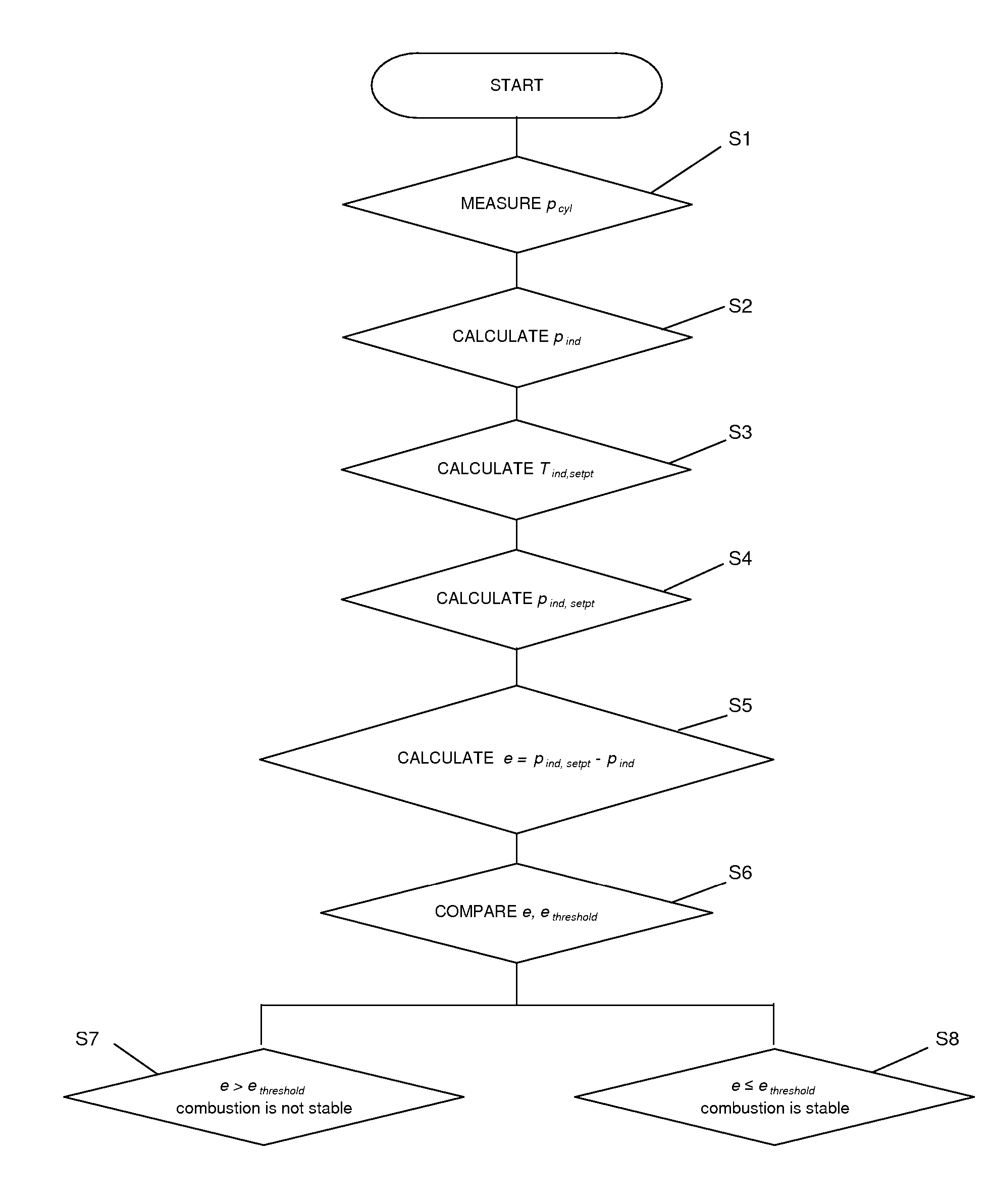
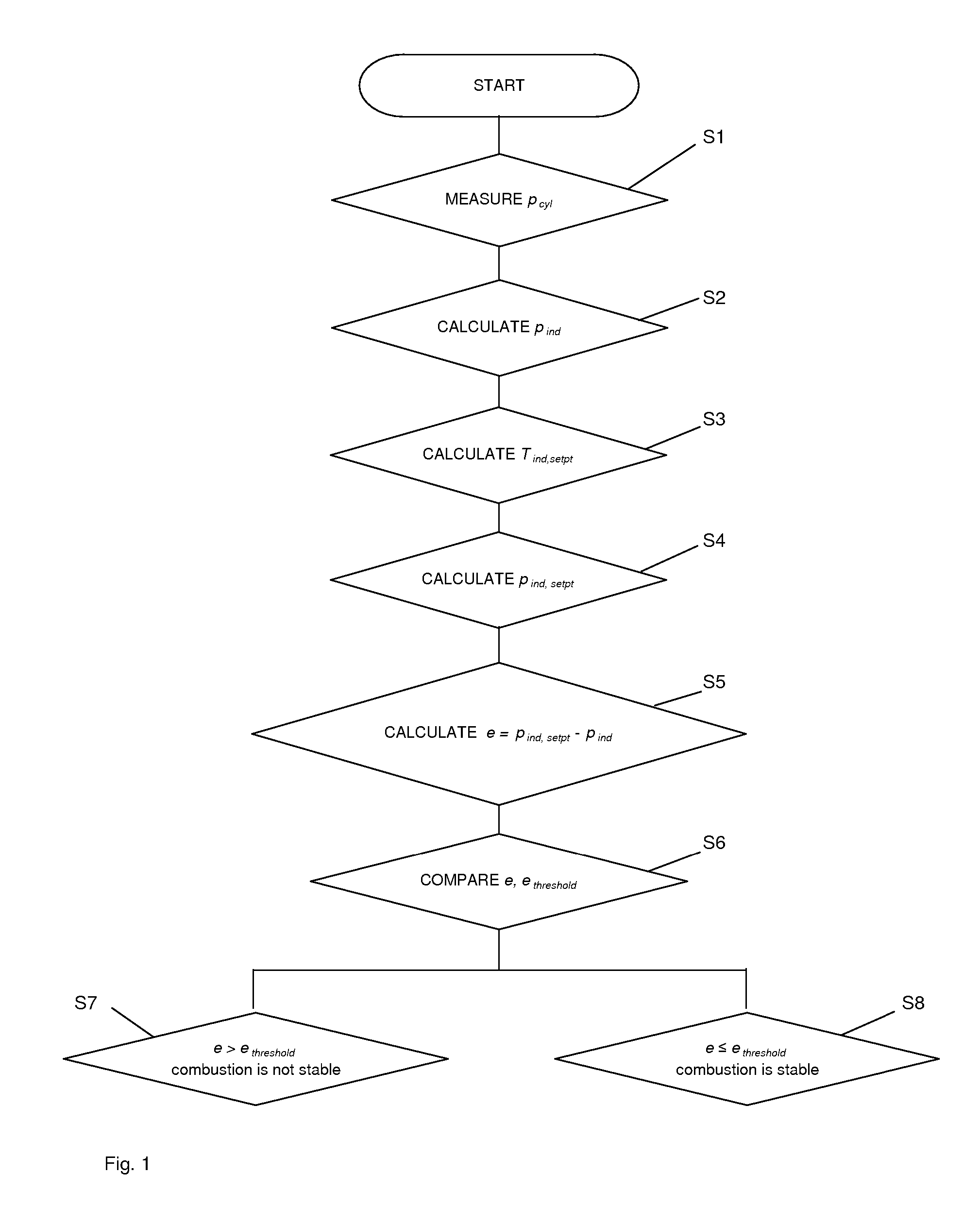
[0063]FIG. 1 shows the flow diagram of a first embodiment according to the invention, wherein in a first step S1 in-cylinder pressure pcyl is measured and used for calculating indicated pressure pind within a second step S2. The torque set point Tind,setpt is determined from the accelerator pedal position (αped), the torque losses and, if necessary, additional signals like engine speed, gear and the like (S3).

[0064] The torque set point Tind,sept is used to determine the set point for indicated pressure pind,setpt in a fourth step S4. For further processing, the deviation e between the set point pind,setpt and the actual value of the indicated pressure pind is calculated (S5).

[0065] The resulting deviation e=Δpind=(Pind−pind,setpt) is compared with a predetermined deviation threshold ethreshold in order to decide whether the combustion is stable or not (S6).

If

|e|>ethreshold

it is assumed that the combustion is not stable (S7a) and has to be stabilized by changing operating cond...

second embodiment

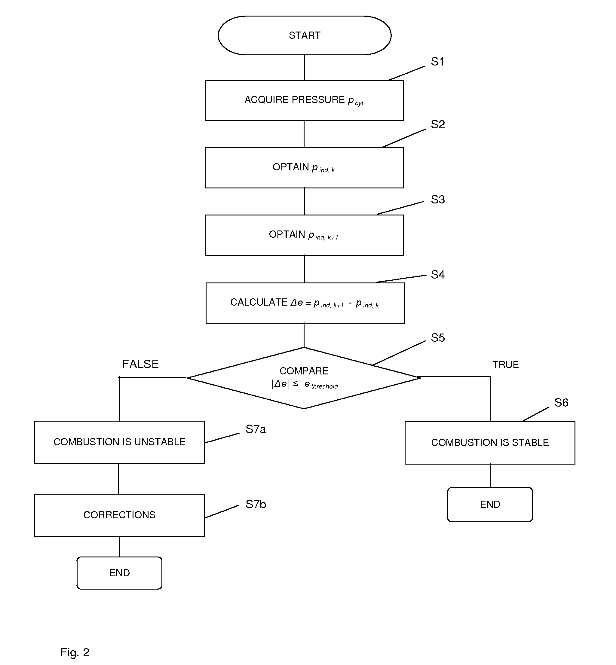
[0066]FIG. 2 shows the flow diagram of a second embodiment according to the invention.

[0067] Within the first step S1 in-cylinder pressure pcyl is measured for two consecutive cycles k, k+1. The respective pressure traces pcyl,k (θ) and pcyl,k+1 (θ) are used to calculate the actual value of indicated pressure pind,k+1 and pind,k for both cycles by integration (S2,S3).

[0068] In practice it will be more convenient to measure in-cylinder pressure pcyl once for one specific cycle and to calculate and store the respective indicated mean effective pressure pind,k for further processing. By doing the same for the consecutive cycle k+1, indicated mean effective pressure is obtained for two consecutive cycles, namely pind,k and pind,k+1, not by recalculating pind each time but by storing the previously calculated value for pind for further processing.

[0069] For further processing the change Δe in deviation between the two cycles in question is calculated (S4) by using the following equatio...


PUM


Abstract

The present invention relates to a method for monitoring combustion stability of an internal combustion engine equipped with a crankshaft, an intake manifold and at least one cylinder, including the following steps: determining the absolute deviation e of indicated mean effective pressure pind or indicated torque Tind with respect to their actual set point, i.e., with respect to actual indicated mean effective pressure set point pind,setpt or actual indicated torque set point Tind,setpt, namely Δpind or ΔTind, or alternatively determining the relative change Δe in said deviation between two consecutive combustion cycles k, k+1 of said at least one cylinder, i.e., determining (Δpind,k+1−pind,k) or (ΔTind,k+1−ΔTind,k) or determining the relative change Δe in angular acceleration ω′ of the crankshaft between two consecutive combustion cycles k, k+1, i.e., (Δω′k+1−Δω′k), and comparing said determinated deviation e or said change Δe with a predetermined engine operating point dependent threshold ethreshold or Δethreshold in order to decide if the combustion is stable or not by means of the following inequalities: |e|>ethreshold or |Δe|>Δethreshold means combustion is not stable, |e|≦ethreshold or |Δe|≦Δethreshold means combustion is stable. The method is preferably applied to homogeneous charge combustion ignition engines (HCCI).

Description

FIELD OF INVENTION [0001] The present invention relates to a method for monitoring combustion stability of an internal combustion engine provided with a crankshaft, an intake manifold and at least one cylinder, and in particular for monitoring combustion stability of an engine operating on the basis of homogeneous charge compression ignition (HCCI). BACKGROUND AND SUMMARY OF THE INVENTION [0002] Traditionally, there have been two different engine types, namely diesel and gasoline engines. Both engines operate with different combustion processes which are different in particular in controlling the start of combustion (SOC). While diesel engines control SOC by the timing of fuel injection, in a gasoline engine, i.e., spark-ignited engine, the SOC is controlled by the spark timing. As a result both combustion processes have different characteristics. [0003] Spark-ignited engines are characterized by low NOx and particulate emissions in comparison to diesel engines. Due to the externall...

Claims


Application Information

Patent Timeline
Patent Type & Authority Applications(United States)
IPC IPC(8): G06G7/70F02M25/07F02B47/08G06F19/00
CPCF02D35/023F02D41/1498F02D2041/286Y02T10/128F02D41/3035Y02T10/12
Inventor CHRISTEN, URSMORAAL, PAULCHEVALIER, ALAINVANTINE, KATIE
Owner FORD GLOBAL TECH LLC
Why Eureka
Try Eureka