

Vapor deposition device
- Summary
- Abstract
- Description
- Claims
- Application Information
AI Technical Summary
Benefits of technology
Problems solved by technology
Method used
Image

Examples
Embodiment Construction
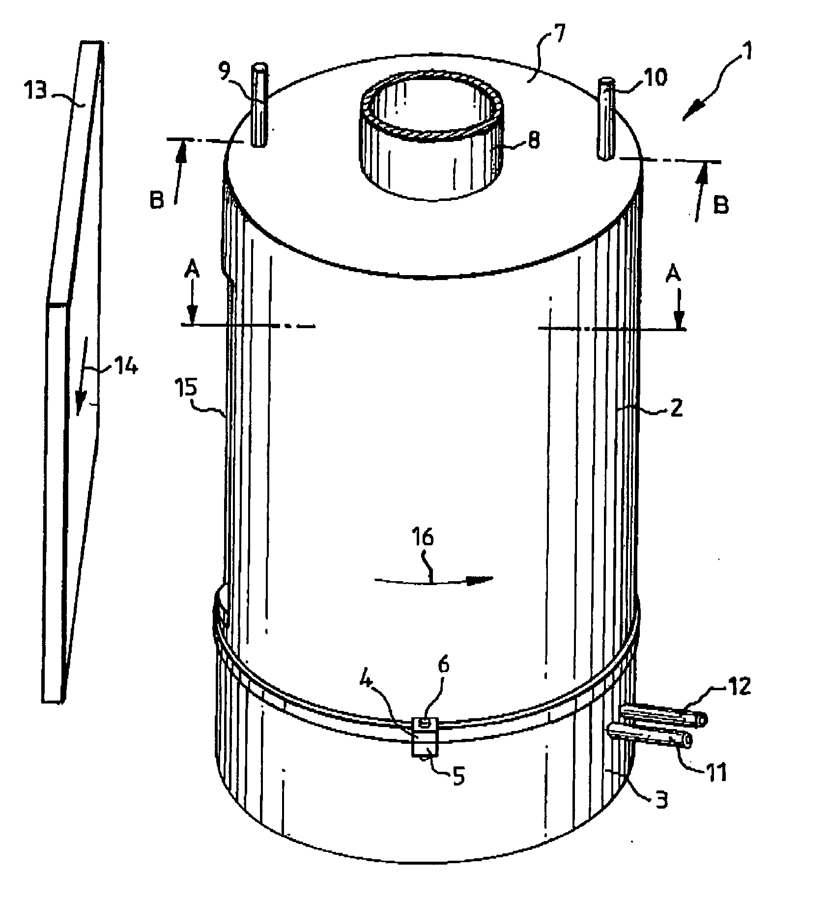
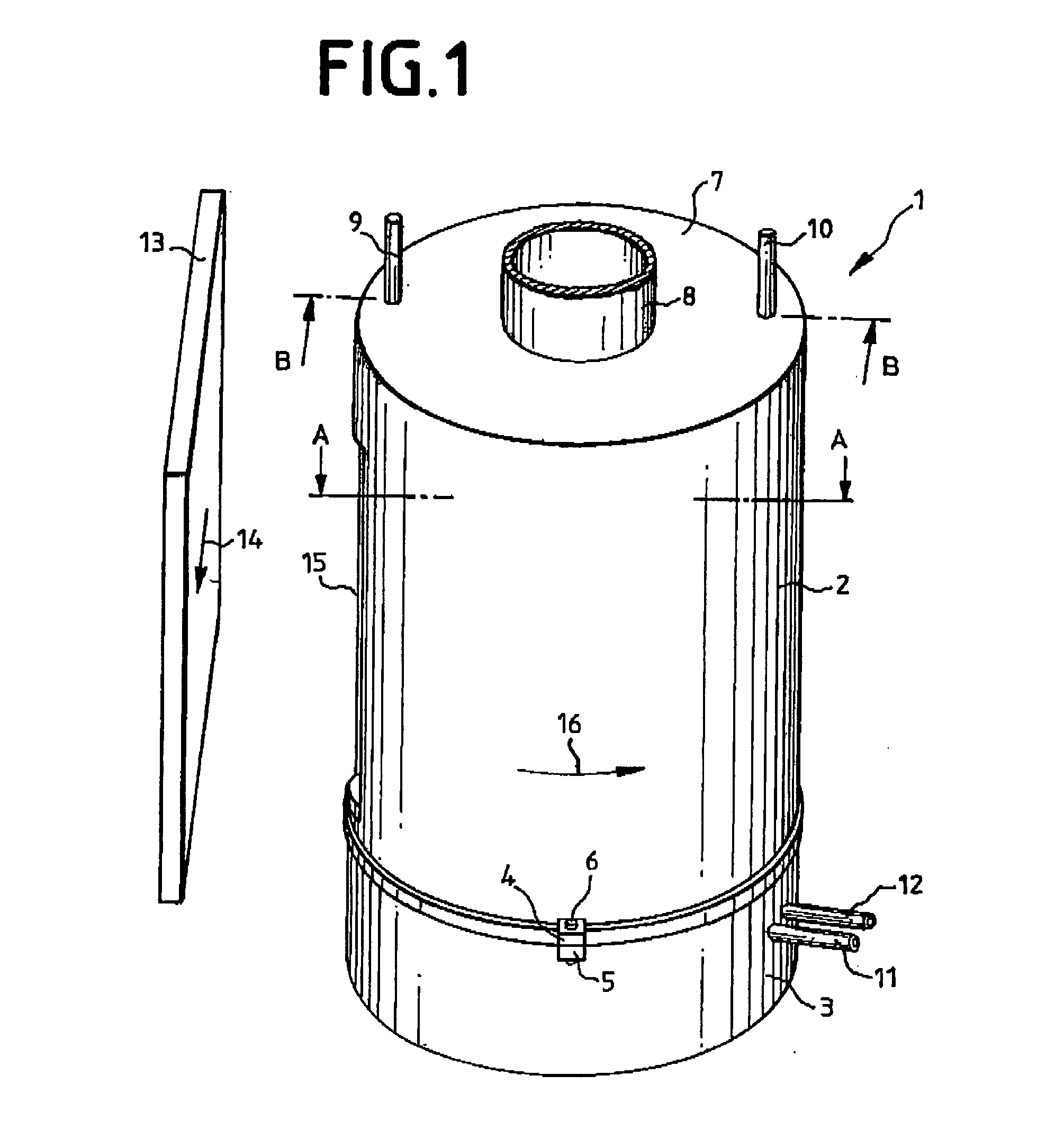
[0024]FIG. 1 depicts a perspective overall view of a vapor deposition device 1 comprising an upper part 2 and a lower part 3. Both parts 2, 3 are held together by an upper and a lower connection clamp 4, 5 as well as by a bolt 6. Several such connection clamps and bolts may be provided over the circumference of the vapor deposition device 1.
[0025] On the top side 7 of the upper part 2 an inlet tube 8 is indicated. By 9 and 10 are denoted cooling means ports, which are also located on the top side of the upper part 2.
[0026] Further cooling means ports 11, 12 are located on the lower part 3.
[0027] The vapor deposition device 1 stands perpendicularly, i.e. parallel to the direction of the gravitational force of the earth. A substrate 13 to be coated, for example a glass plate coated with OLED, is guided past the vapor deposition device 1, and specifically horizontally, as indicated by arrow 14. The OLED may be disposed on an ITO layer, which forms a first electrode. The metal layer ...
PUM
| Property | Measurement | Unit |
|---|---|---|
| Force | aaaaa | aaaaa |
| Shape | aaaaa | aaaaa |
| Thermal conductivity | aaaaa | aaaaa |
Abstract
Description
Claims
Application Information