Automatic extension of clock gating technique to fine-grained power gating

Active Publication Date: 2007-02-01
ANSYS
View PDF2 Cites 64 Cited by
  • Summary
  • Abstract
  • Description
  • Claims
  • Application Information

AI Technical Summary

Benefits of technology

[0008] The present invention provides a technique to automatically extend a clock-gated design for fine-grained power gating. Using this te

Problems solved by technology

However, both these techniques require adding significant amount of additional logic circuits to generate the sleep signal needed for power gating.
T

Method used


Image

  • Automatic extension of clock gating technique to fine-grained power gating
  • Automatic extension of clock gating technique to fine-grained power gating
  • Automatic extension of clock gating technique to fine-grained power gating

Examples


Embodiment Construction

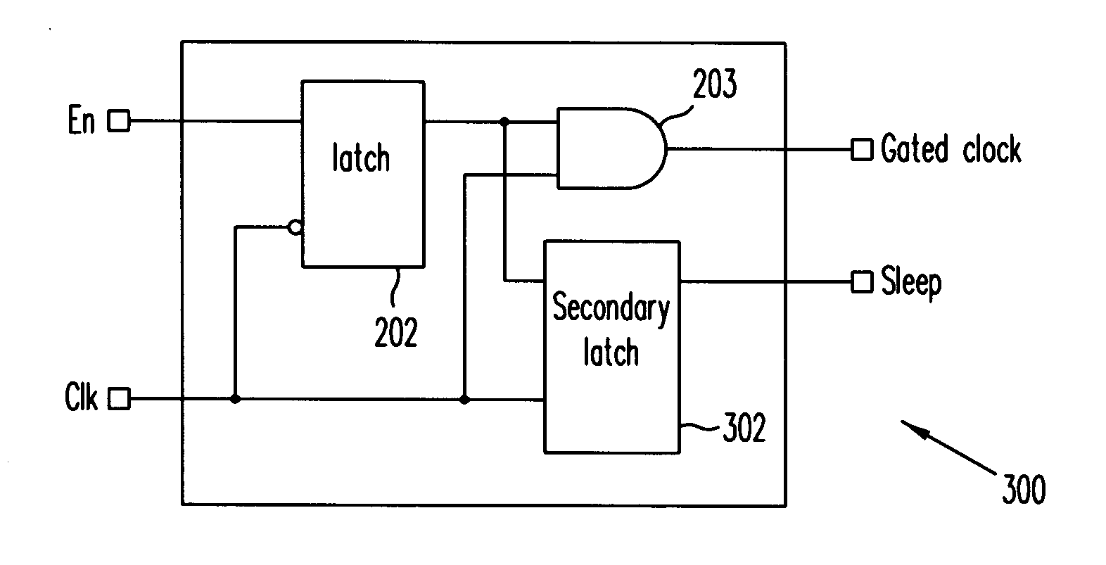
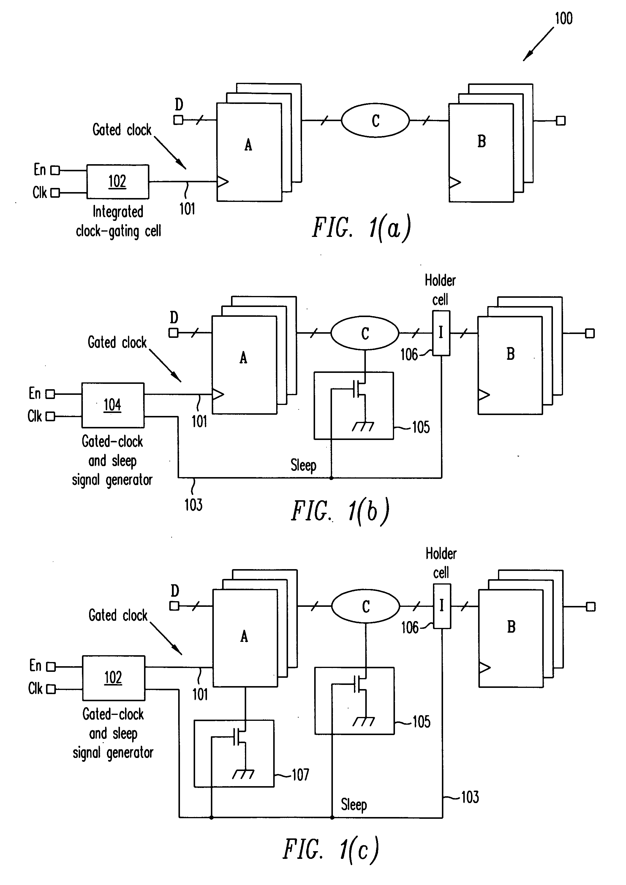
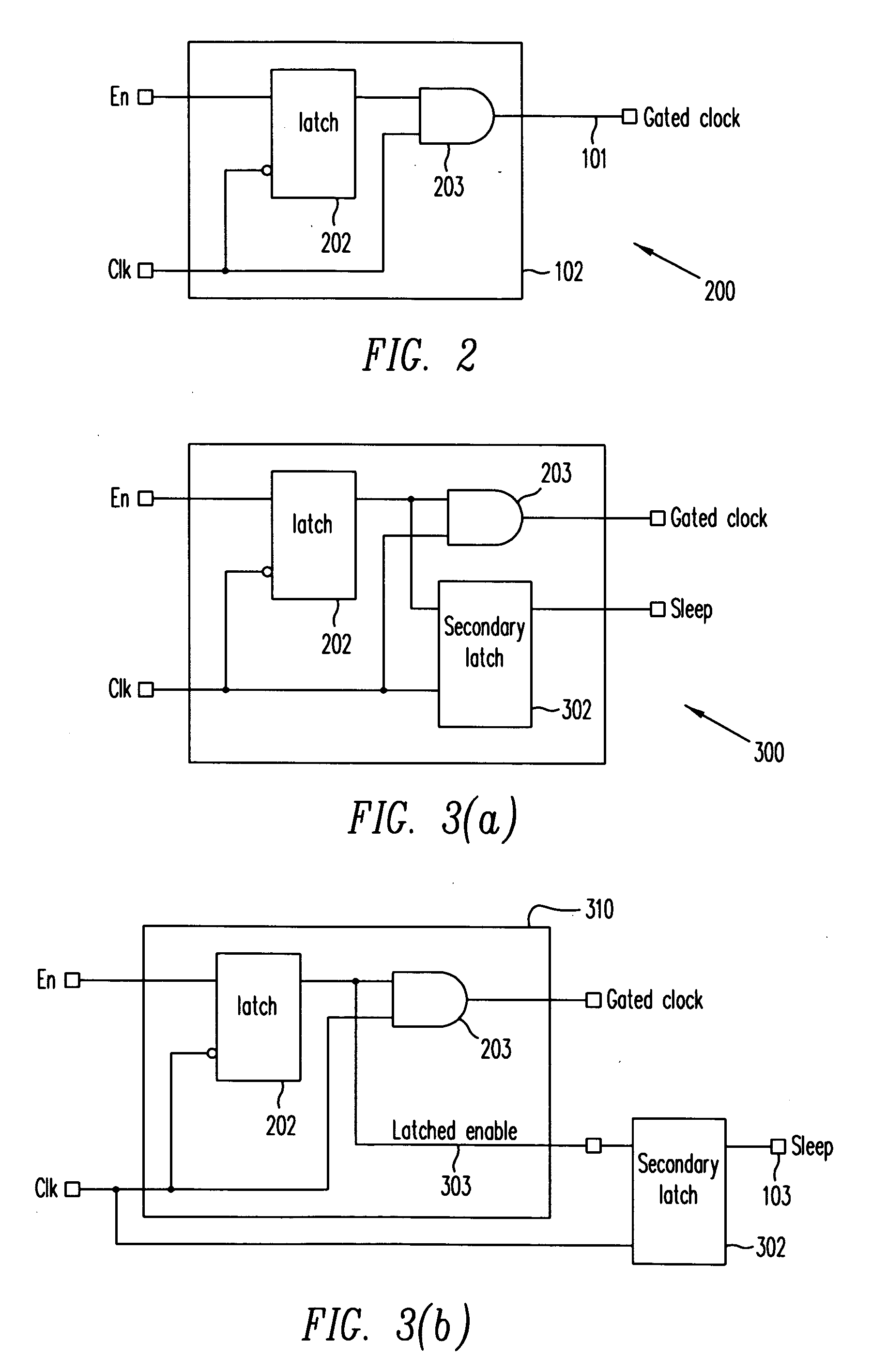
[0022] Clock-gating is a technique that reduces clock power dissipation. FIG. 1(a) illustrates clock-gated circuit 100 schematically. As shown in FIG. 1(a), register set A receives a clock signal 101 that results from gating clock signal “clk” with enable signal, “En” in an “integrated clock-gating cell”102. The power dissipated by circuit propagating clock signal “clk” is termed “dynamic power dissipation.” Clearly, by disabling propagation of clock signal “clk”, dynamic power dissipation in the circuits clocked by clock signal “clk” and its derivative signals is reduced. FIG. 2 shows structure 200, which is an example of an integrated clock-gating (ICG) cell. As shown in FIG. 2, gated-clock signal 102 is provided by gating clock signal “clk” with the output signal of latch 202 in AND gate 203. Latch 202 may be implemented, for example, by a level-sensitive latch that transfers the logic value of enable signal “En” during the low logic level of clock signal “clk”.

[0023] The invent...


PUM


Abstract

A method extends a clock-gating technique to provide a sleep signal for controlling switch circuits that reduce active leakage power. Using this extension of the clock-gating technique, fine-grained power-gating is achieved. The method automatically identifies, at an RTL or a gate level, the logic circuits that can be power-gated. The method of the present invention derives a sleep signal for fine-grained power-gating that may be applicable to both time-critical and non-time-critical designs.

Description

BACKGROUND OF THE INVENTION [0001] 1. Field of the Invention [0002] The present invention relates to techniques for creating low-power integrated circuits. In particular, the present invention relates to techniques designed for creating low-power integrated circuits using a power-gating technique. [0003] 2. Discussion of the Related Art [0004] Power-gating is a circuit level technique applicable to, for example, multi-threshold CMOS (MTCMOS) circuits to reduce leakage power (i.e., to reduce power dissipation due to leakage current). In power-gating, a switch cell is introduced between a functional circuit and a power supply voltage reference or a ground voltage reference, so that the functional circuit can be selectively electrically connected or disconnected from a power source or the ground reference by deasserting or asserting a sleep signal. A switch cell may be implemented by a PMOS or a NMOS transistor, depending on whether the connection to the power supply voltage reference ...

Claims


Application Information

Patent Timeline
IPC IPC(8): H03K19/173
CPCH03K19/0016
Inventor MAMIDIPAKA, MAHESH
Owner ANSYS
Why Eureka
Try Eureka