
Image processing device

a technology of image processing and processing device, which is applied in the field of image processing apparatus, can solve the problems of chromatic aberration, distortion aberration, and general distortion of 98/b>, and achieve the effect of reducing processing and reducing processing

Active Publication Date: 2007-02-01
OLYMPUS CORP
View PDF7 Cites 50 Cited by
  • Summary
  • Abstract
  • Description
  • Claims
  • Application Information

AI Technical Summary

Benefits of technology

[0031] Further, according to the present invention, an image processing apparatus for performing image processing, including distortion correction processing and enlarging and reducing processing, of electronic image data obtained by capturing an image via an optical system, comprises a distortion correction processing unit. The distortion correction processing unit comprises: an interpolating-coordinate generating unit that generates interpolating coordinate data, serving as coordinate data before interpolating processing, corresponding to the pixel position after the interpolating processing of the imag...

Problems solved by technology

The large load to the bus 98 is more serious in the use of continuous image pickup operation.
In a camera optical system including a digital camera or a silver-halide camera, although varied, a distortion aberration is generally caused.
Further, in the camera optical system, it is well-known that a chromatic aberration is caused.
However, all the chromatic aberrations are not removed in view of arrangement space, weight, and costs.
Therefore, the buffer needs a relatively large capacity to obtain the corrected image of one line, the circuit scale increases, manufacturing costs increase, and the power consumption raises.
Further, the processable image size is limited, depending on the capacity of buffer memory in the image processing unit.
However, both the processings need interpolation and calculation every pixel and the processing circuit has a large scale.
Thus, mere adoption of the configuration having both the processing circuits increases the circuit scale.
Further, the power consumption increases and the manufacturing costs raise.

Method used


Image

  • Image processing device
  • Image processing device
  • Image processing device

Examples


first embodiment

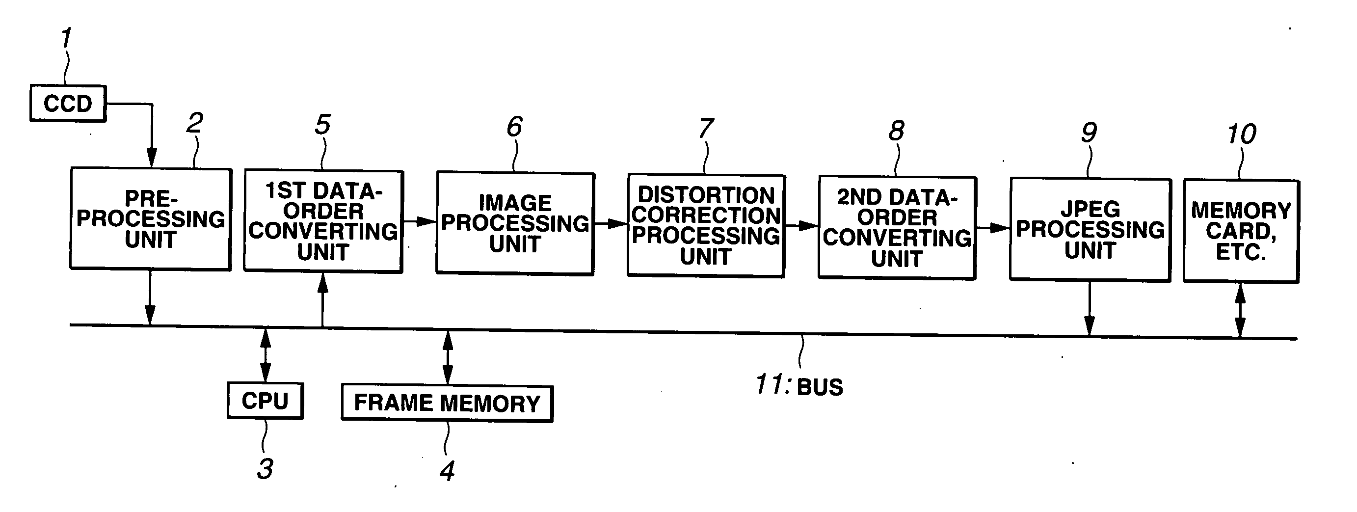
[0068] FIGS. 1 to 14 show the present invention. FIG. 1 is a block diagram showing the configuration of an image processing apparatus.

[0069] The image processing apparatus comprises: a CCD 1, serving as an image pickup element, which photoelectrically converts an optical subject image formed by an optical system and generates an electrical image pickup signal; a pre-processing unit 2 which performs pre-processing, such as correction of pixel defect or A / D conversion of the image pickup signal outputted from the CCD 1; a frame memory 4 which stores a frame image after procession by the pre-processing unit 2; a first data-order converting unit 5 which reads image data stored in the frame memory 4 every predetermined block via a bus 11, which will be described later, temporarily stores the data, and thereafter changes the reading order and outputs the data; an image processing unit 6, serving as an image processing unit, which performs predetermined image processing of the image data o...

second embodiment

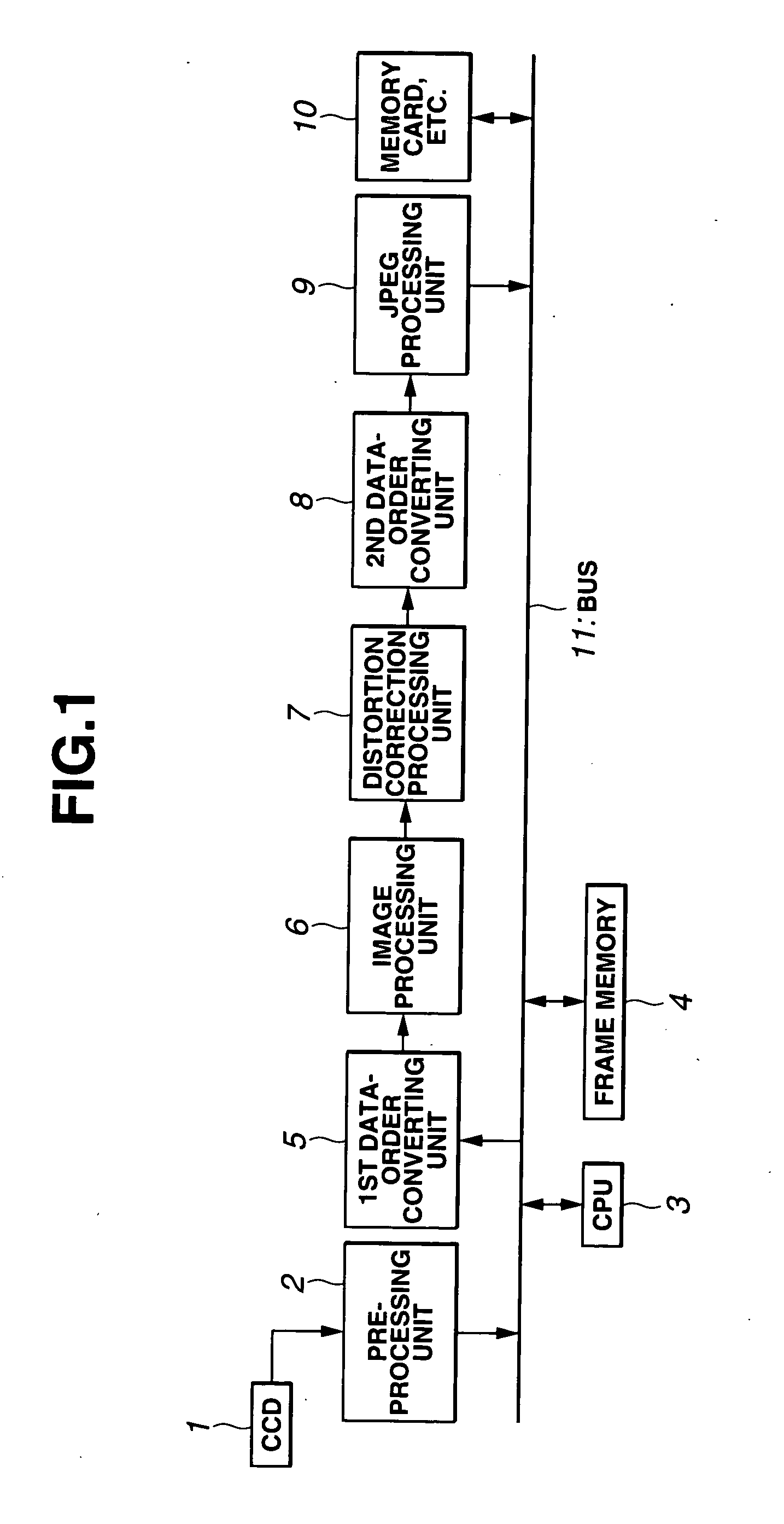
[0128] FIGS. 15 to 20 show the present invention, and FIG. 15 is a block diagram showing the configuration of an image processing apparatus.

[0129] According to the second embodiment, the same portions as those according to the first embodiment are not described and different portions are mainly described.

[0130] The image processing apparatus according to the second embodiment comprises components excluding the first data-order converting unit 5 and the second data-order converting unit 8 from the image processing apparatus shown in FIG. 1 according to the first embodiment.

[0131] Further, the distortion correction processing unit 7, serving as an image processing unit and distortion correction processing means, according to the second embodiment performs the enlarging and reducing processing as well as the distortion correction processing of the image data after the procession by the image processing unit 6.

[0132] Similarly to the foregoing, the image processing unit 6, the distor...

third embodiment

[0212] FIGS. 21 to 31 show the present invention. According to the third embodiment, the same portions as those according to the first and second embodiments are not described and only different portions are mainly described.

[0213] The configuration of a main portion of the image processing apparatus according to the third embodiment is similar to that shown in FIG. 15 according to the second embodiment.

[0214] An inner buffer for reducing the capacity by transferring the image data in units of a predetermined number of blocks is an inner memory unit 25 shown in FIG. 2 or a 2-port SRAM 25a shown in FIG. 29 according to the third embodiment.

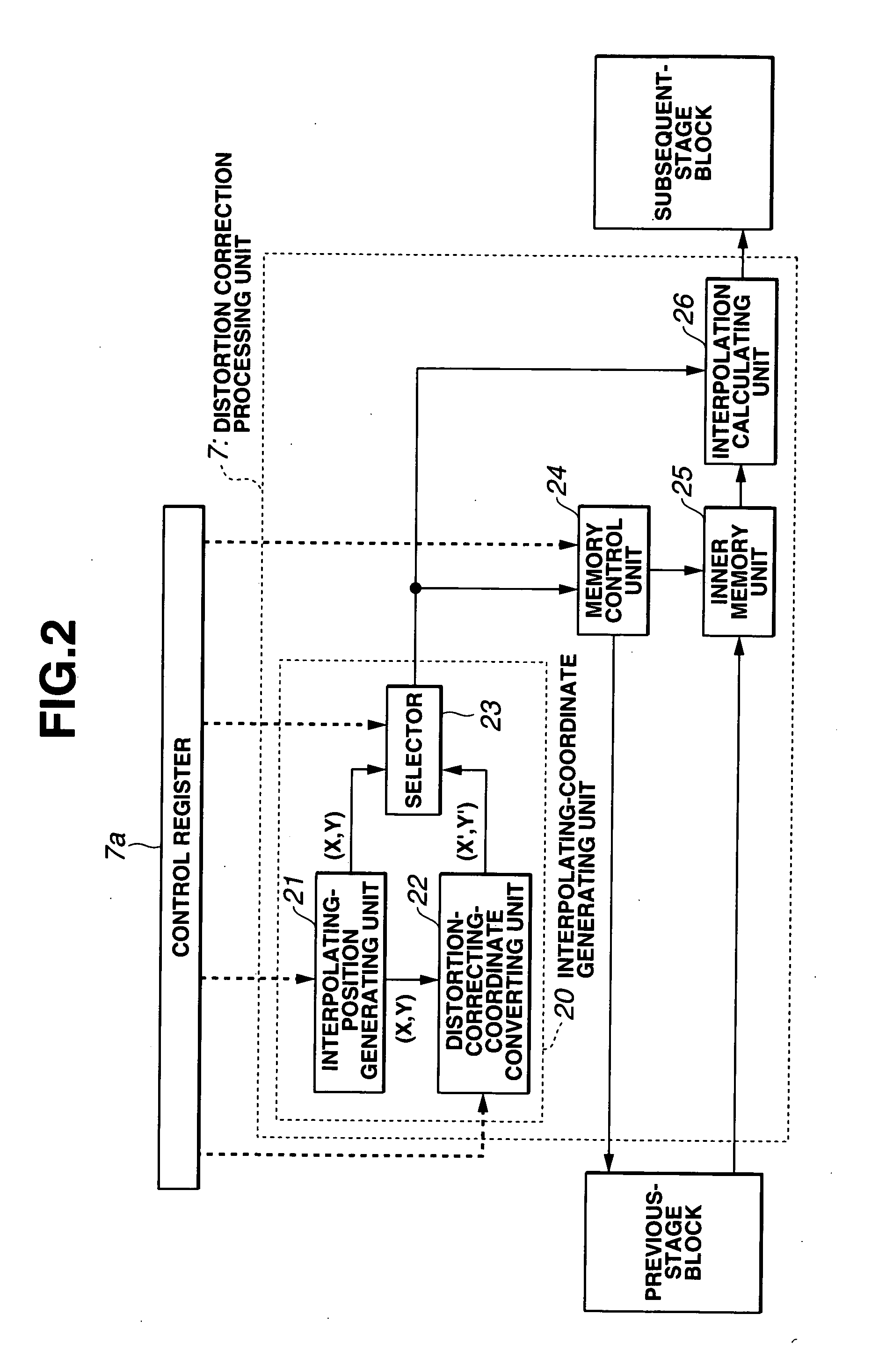
[0215]FIG. 21 is a block diagram showing the configuration of the distortion correction processing unit 7.

[0216] The color image data is generally resolved into three (or more) independent signal components, such as RGB and YCbCr signals, and then is processed every component. Here, a description is given of channels Ch.0, Ch.1, and Ch.2 for pro...


PUM


Abstract

An image processing apparatus applied to a digital camera, includes: a frame memory that inputs and stores, via a bus, image data obtained by capturing an optical image through an optical system by a CCD; a first data-order converting unit that reads and inputs the image data from the frame memory in units of a block in the row direction, and converts and outputs the image data in the column direction; an image processing unit that is connected to the first data-order converting unit for pipeline processing and performs image processing; a distortion correction processing unit that is connected to the image processing unit for pipeline processing and performs the distortion correction processing; and a second data-order converting unit that is connected to the distortion correction processing unit for pipeline processing, returns block data in the column direction into that in the row direction, and outputs the converted data to the frame memory.

Description

CROSS REFERENCE TO RELATED APPLICATION [0001] This application is a continuation application of PCT / JP2004 / 007855 filed on May 31, 2004 and claims the benefit of Japanese Applications No. 2003-157044 filed in Japan on Jun. 2, 2003, No. 2003-177290 filed in Japan on Jun. 20, 2003, and No. 2003-177291 filed in Japan on Jun. 20, 2003 the entire contents of each of which are incorporated herein by their reference. BACKGROUND OF THE INVENTION [0002] 1. Field of the Invention [0003] The present invention relates to an image processing apparatus, and more particularly, to an image processing apparatus for processing electronic image data captured via an optical system. [0004] 2. Description of the Related Art [0005] In general, in an electronic image pickup device, such as a digital camera, a subject image formed via an optical system is photoelectrically converted by an image pickup element, such as, a CCD, image pickup data is obtained, and the image pickup data is subjected to various i...

Claims


Application Information

Patent Timeline
IPC IPC(8): G06K9/40G06T1/20G06T3/00G06T5/00H04N1/393H04N5/10
CPCG06T1/60H04N25/61
Inventor FURUKAWA, HIDEAKIHIGURASHI, MASAKIUENO, AKIRA
Owner OLYMPUS CORP
Features
  • Generate Ideas
  • Intellectual Property
  • Life Sciences
  • Materials
  • Tech Scout
  • Unparalleled Data Quality
  • Higher Quality Content
  • 60% Fewer Hallucinations
Learn More