
Fluid Proportioning Valve

a proportional valve and valve body technology, applied in the field of valves, can solve the problems of turbine tripping off-line, high output requires significant fuel consumption, and the operation of the metering valve used, and achieves high stability of metering, low leakage, and high resistance to material contamination.

Active Publication Date: 2007-02-08
JANSENS AIRCRAFT SYST CONTROLS
View PDF9 Cites 3 Cited by
  • Summary
  • Abstract
  • Description
  • Claims
  • Application Information

AI Technical Summary

Benefits of technology

[0010] The present invention provides a fluid proportioning valve for metering flow of pressurized fluid in proportion to the pressure drop between the inlet and outlet of the valve. Various features of the valve provide for highly stable metering and low leakage and make it highly resistant to material contamination and galling of the metering element with minimal parasitic pressure losses. Operational parameters of the valve are easily adjusted by changing the return force member, and the valve assembly can be in a cartridge form to allow for quick assembly into the main housing and changing of valve assemblies of different operational parameters.
[0012] The valve can be flow pressure activated with spring return. In particular, the metering valve can be an inverted spool type annular poppet valve that fits about the annular body of the valve guide. For example, the valve can be cylindrical with a circular cross-section and a circular metering edge, preferably being tapered in the direction of the inlet flow. The metering edge thus shears the across the metered flow stream so that the metering valve is essentially insensitive to flow forces, thereby providing highly stable metering and valve operation.
[0013] The valve guide can define a plurality of the orifices in communication with the valve guide inlet. The valve orifices are spaced apart along a circumference of the valve guide. Multiple, small valve orifices reduces local flow forces on the valve metering edge, reducing valve chatter and improving stability.
[0015] Using a spring of a different spring rate or turn count allows for simple pressure crack adjustment of the valve. Moreover, spring resonance interaction with the flow media is avoided by isolating the spring from the flow media.
[0017] The valve thus maximizes the clearance between the sliding poppet valve and the stationary valve guide. The buttons also prevent sliding surface contact as well as metal-to-metal contact between the poppet valve and the valve guide. This eliminates galling and improves resistance to particle contamination of the flow stream. The smooth contour flow path through the valve further reduces particle contamination by reducing air pockets where particles can build up.

Problems solved by technology

Such high output requires significant fuel consumption on the order of 200-400 gallons per minute.
Given the high flow requirements of large industrial turbine systems, the proper operation of the metering valves used to control water injection is critical.
Failure of the metering valve can lead to the turbine tripping off-line.
Tripping off-line can be harmful to the moving elements of the turbine and leaves the turbine inoperable for lengthy periods while the problem is addressed and the turbine is brought back on-line.
Problems are encountered with existing metering valves with respect to valve stability, leakage and particle contamination, among other things.
The high flow rate environment in which the valve operates gives rise to high flow forces acting on the metering member of the valve.
These flow forces acting on the metering member can cause disruptions or slight position changes of the metering edge at the interface with the metering orifice(s).
This “chatter” in turn leads fluctuations in the metered flow and thereby transient or sustained instability.
The high flow rates and flow forces can also cause seal failure resulting in valve leakage.
Valve operation can also be adversely affected by the build up of particles in the flow path.
Close tolerances and sliding metal-to-metal contact can cause either the metering member or the seat, or both, to wear and introduce particles into the internal areas of the valve.
In addition to causing galling, these particles can impair movement of the metering member or disturb the metering edge / orifice interface.
All of these things impact valve operation and can lead to untimely turbine shut-down and thereby loss of plant power output.

Method used


Image

  • Fluid Proportioning Valve
  • Fluid Proportioning Valve
  • Fluid Proportioning Valve

Examples


Embodiment Construction

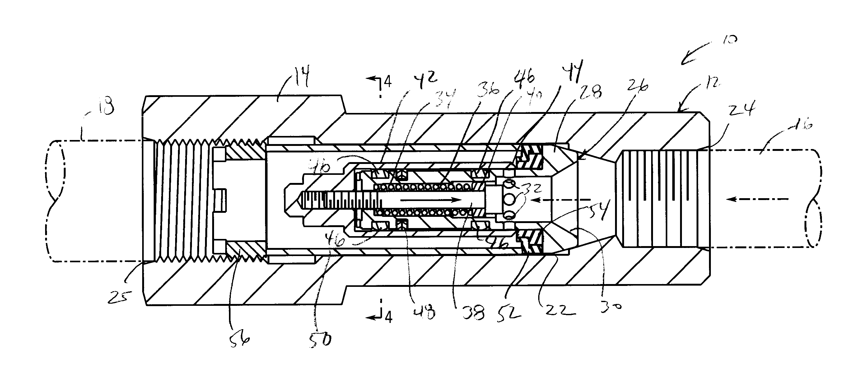
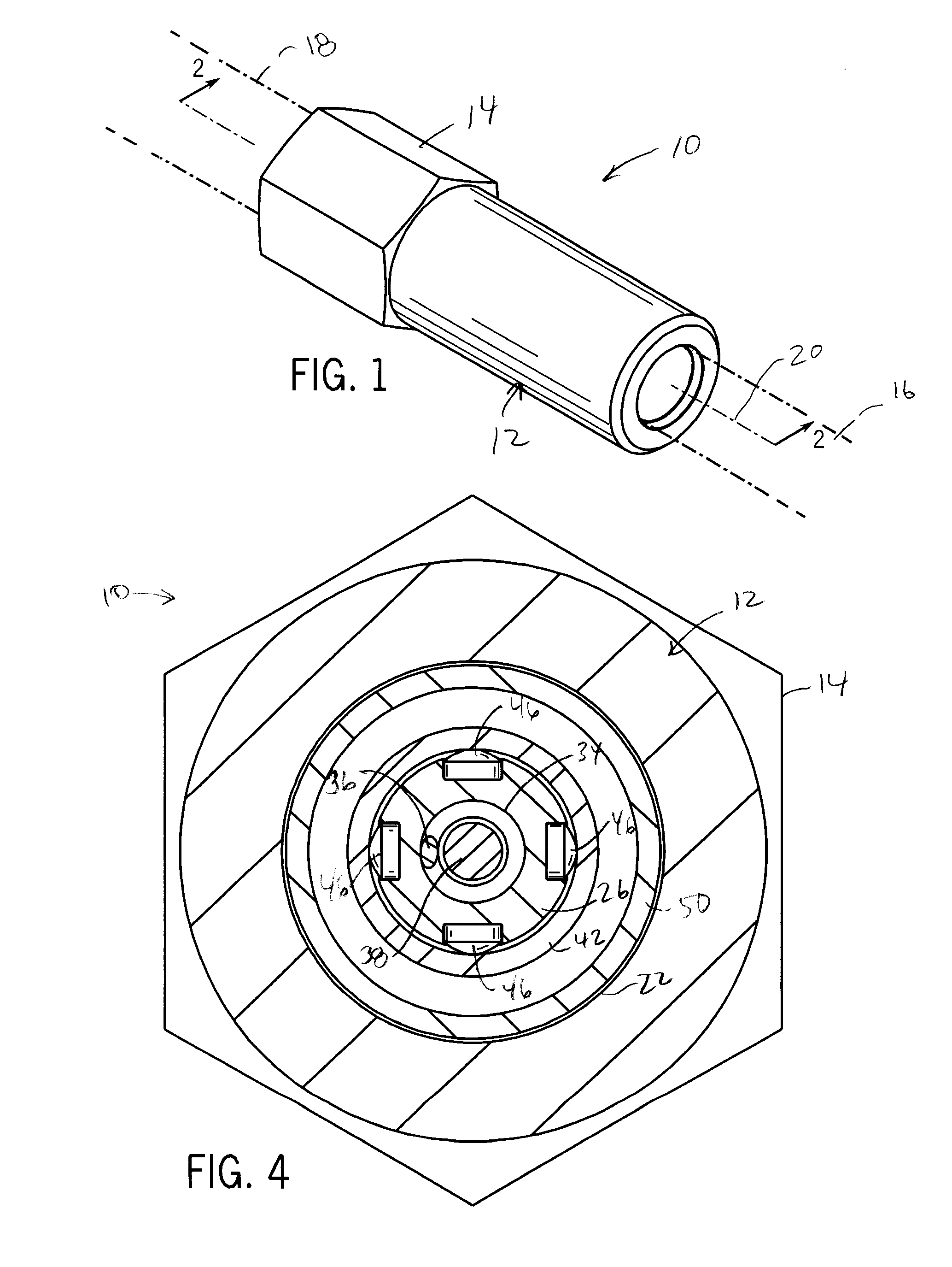
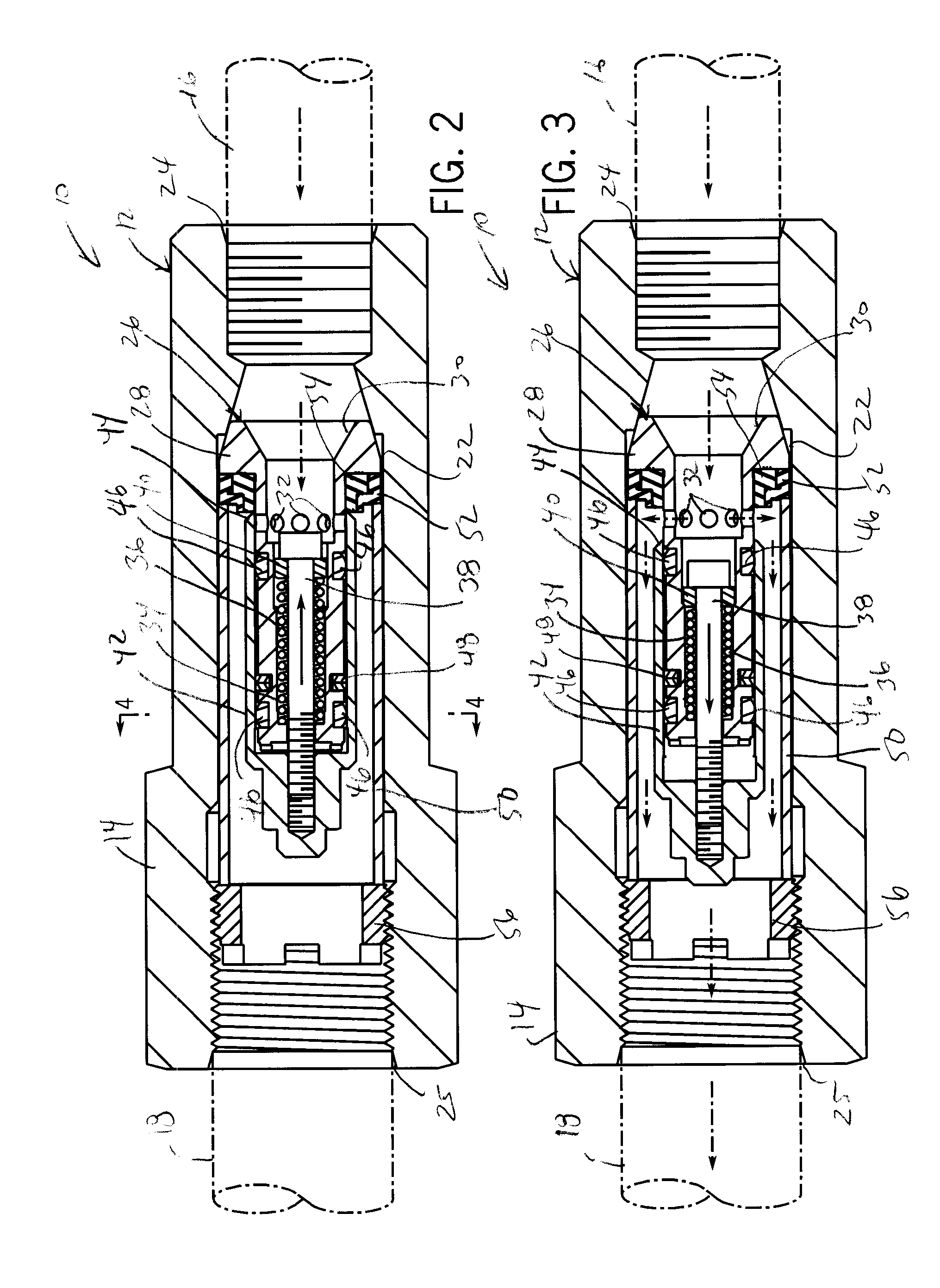
[0023]FIG. 1 shows a preferred version of the proportioning valve 10 of the present invention. The proportioning valve 10 has an annular housing 12 with an external hex section 14 for application of tooling when assembling the proportioning valve 10 inlet 16 and outlet 18 lines (shown in phantom in FIGS. 1 and 2). The valve housing 12 extends about and along valve axis 20 and defines an internal valve cavity 22 in communication with an inlet port 24 and an outlet port 25. Both ports are threaded internally, and the valve cavity 22 has a partial conical section that tapers inwardly to the inlet port 24.

[0024] As shown in FIGS. 2 and 3, the valve cavity 22 contains the internal working components of the proportioning valve 10. The internal components are packaged as a compact cartridge assembly for ease of installation and so that the operational parameters of the valve can be changed simply by swapping one cartridge assembly with another.

[0025] In particular, the cartridge assembly...


PUM


Abstract

A fluid proportioning valve meters flow of pressurized inlet fluid in proportion to a pressure drop between the inlet and outlet of the valve. A pressure acutated, return biased poppet valve is actuated by the fluid above threshold fluid pressure to meter fluid to the outlet against spring force. The poppet is annular and has a circular metering edge that controls flow through circumferential orifices in a valve guide. Smooth stable flow is achieved by shearing action of the metering edge over the orifices. Sliding point contact with the poppet valve by non-ferrous convex buttons to eliminate galling and reduce particle contamination within the valve.

Description

CROSS-REFERENCE TO RELATED APPLICATIONS [0001] This application claims benefit to U.S. provisional application Ser. No. 60 / 706,156, filed Aug. 5, 2005 and U.S. provisional application Ser. No. 60 / 746,571, filed May 5, 2006.STATEMENT OF FEDERALLY SPONSORED RESEARCH OR DEVELOPMENT [0002] Not applicable. BACKGROUND OF THE INVENTION [0003] 1. Technical Field [0004] The present invention relates to valves, and in particular, to proportional valves in which the output flow is proportional to the pressure drop across the valve. [0005] 2. Description of the Related Art [0006] Modern gas turbines used in the generation are very large and capable of a continuous power output between 200-500 megawatts. Such high output requires significant fuel consumption on the order of 200-400 gallons per minute. Water can be injected into the combustion chambers to reduce emissions from the turbine. Water injection also serves to increase maximum power output of the turbine by increasing mass flow through ...

Claims


Application Information

Patent Timeline
IPC IPC(8): F16K31/36
CPCF16K15/063F16K17/0433F16K17/0426Y10T137/7504Y10T137/7834Y10T137/7783
Inventor JANSEN, HARVEY B.
Owner JANSENS AIRCRAFT SYST CONTROLS
Learn More