Method and apparatus for compensating for atmospheric turbulence based on holographic atmospheric turbulence sampling

a technology of atmospheric turbulence and atmospheric turbulence, applied in the field of linear phase conjugation atmospheric turbulence compensation, can solve the problems of affecting the beam that finally reaches the target, affecting the beam that reaches the target, and lasers propagated over any distance in the atmosphere suffer from a significant decrease in fluence at the target, and achieves a much-enhanced signal-to-noise ratio

Inactive Publication Date: 2007-02-08
BAE SYST INFORMATION & ELECTRONICS SYST INTERGRATION INC
View PDF6 Cites 24 Cited by
  • Summary
  • Abstract
  • Description
  • Claims
  • Application Information

AI Technical Summary

Benefits of technology

[0028] The result is to be able to correct for atmospheric turbulence in near-real time, with the holographic technique having the benefit of simplicity. One does not need a lateral shearing interferometer, which is a relatively complex device; and does not need complex interferometric techniques.
[0029] In order for the subject system to work better with non-cooperative dispersive targets, a bootstrapping method is employed to build up signals from the noise level to usable signals. In bootstrapping, one reverses the effects of atmospheric turbulence in a multi-step process. First one reflects a first pulse from the probe beam off of the spatial light modulator and propagates it out towards the target. One then generates a first hologram from the target returns characterized by small intensity areas on the hologram at the focal plane of the CCD camera. In this first pass one is able to obtain information about the atmosphere between the laser and the target. This information is used to generate a phase conjugate that configures the face of the spatial light modulator.
[0031] Thereafter, the engagement laser projects a pulse towards the spatial light modulator. Because the last of the successive phase conjugates reflects a much-enhanced signal-to-noise ratio, the wavefronts of the engagement laser pulses are robustly compensated.
[0032] This iterative bootstrapping process converges to a solution in, for instance, as little as three pulses, building up the atmospheric turbulence signal from the noise. This means that one can work with very noisy holograms and by bootstrapping permit diffuse, far-off targets to be illuminated with near diffraction-limited engagement laser beams.

Problems solved by technology

Atmosphere-induced aberrations can seriously degrade laser performance, greatly affecting the beam that finally reaches a target.
Lasers propagated over any distance in the atmosphere suffer from a significant decrease in fluence at the target due to atmospheric aberrations.
With atmosphere-induced aberrations, the effect on the beam width of a laser beam can be severe such that the fluence on the target is spread over a wide area.
In target designators, having a large area of the target illuminated may result in both non-lethal hits (enlarged circular error probability (CEP)) or not enough reflected energy to track on.
However, atmospheric turbulence or platform motion results in a lack of fine aim point control to effectively keep a beam directed to a target.
The aforementioned deformable mirror or rubber mirror systems unfortunately can suffer from issues such as high system cost, high system complexity and the fact that one needs a lateral shearing interferometer.
Using true sodium-D lines, however, can be a challenge because one needs a specific laser wavelength to excite the specific transition and one then needs to correct the outgoing laser beam not only based on the specific transition sensed but also on offset between the transition and the actual laser wavelength.
However, if one is in a tactical or a strategic military application, one does not want to base the correction for the atmospheric turbulence upon a cooperative return because one might not in fact have a cooperative return.

Method used


Image

  • Method and apparatus for compensating for atmospheric turbulence based on holographic atmospheric turbulence sampling
  • Method and apparatus for compensating for atmospheric turbulence based on holographic atmospheric turbulence sampling
  • Method and apparatus for compensating for atmospheric turbulence based on holographic atmospheric turbulence sampling

Examples


Embodiment Construction

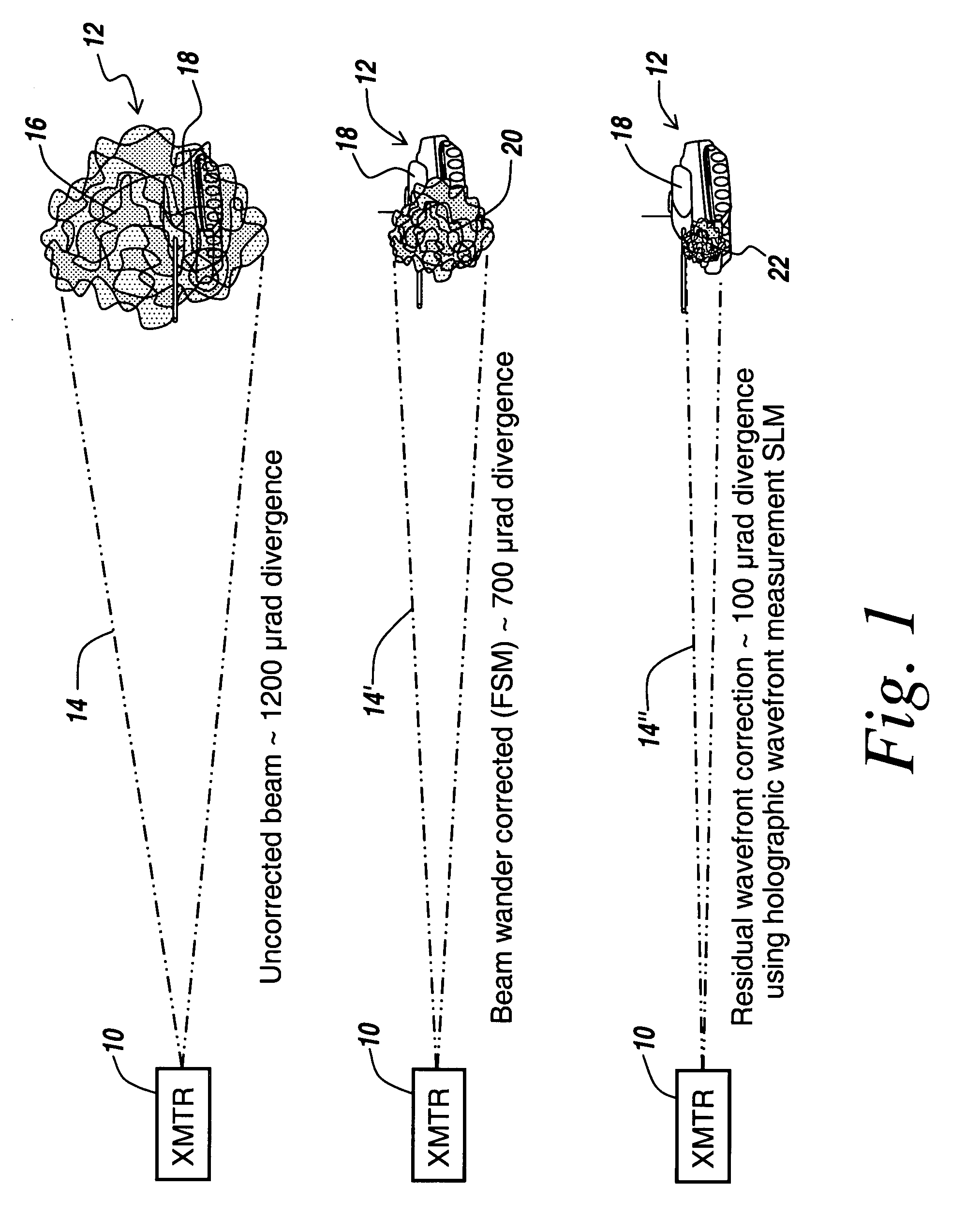
[0040] Referring now to FIG. 1, there are a series of diagrams involving the beam spread of a laser beam, which beam spread is due to atmospheric turbulence between a transmitter 10 and a target area 12.

[0041] For an uncorrected laser beam there can be as much as a 1200 microradian divergence of beam 14 such that at the target area the area subtended by the beam, here illustrated at 16, is relatively large and can, for instance, be much larger than the target that is intended to be illuminated.

[0042] If beam 14 is wander-corrected as illustrated by beam 14′, meaning corrected by SFM techniques, then one could expect an approximate 700-microradian divergence, which would paint a target 18 with a relatively wide illumination pattern 20 that in this case completely obscures the target. More importantly, it is impossible with the wander-corrected beam to be able to pinpoint a part on a target for which a kill would be maximally effective.

[0043] As can be seen from beam 14″, the resid...


PUM


Abstract

A method is presented utilizing a holographic approach for linear phase conjugation to compensate for atmosphere-induce aberrations that severely limit laser performance. In an effort to improve beam quality, fine aim point control, and laser energy delivered to the target, aberration compensation is accomplished using holographic adaptive tracking that utilizes a spatial light modulator as a dynamic wavefront-reversing element to undo aberrations induced by the atmosphere, platform motion, or both. This aberration compensation technique results in a high fidelity, near-diffraction limited laser beam delivered to the target.

Description

RELATED APPLICATIONS [0001] This Application claims rights under 35 USC § 119(e) from U.S. Application Ser. No. 60 / 705,137 filed Aug. 3, 2005, the contents of which are incorporated herein by reference.FIELD OF THE INVENTION [0002] This invention relates to linear phase conjugation atmospheric turbulence compensation and more particularly to real-time holographic interactive media sampling to generate a holographic phase conjugate used to reconfigure the wavefront of an outgoing laser beam to cancel out the effects of atmospheric turbulence. BACKGROUND OF THE INVENTION [0003] Atmosphere-induced aberrations can seriously degrade laser performance, greatly affecting the beam that finally reaches a target. This is especially true for propagation close to the ground and over long distances. Lasers propagated over any distance in the atmosphere suffer from a significant decrease in fluence at the target due to atmospheric aberrations. This is primarily due to fluctuations in the atmosphe...

Claims


Application Information

Patent Timeline
Patent Type & Authority Applications(United States)
IPC IPC(8): G03H1/08
CPCG03H1/0005G03H1/08G03H1/12G03H2001/0066G03H2225/22G03H2001/0447G03H2001/0816G03H2210/63G03H2001/0083
Inventor GRASSO, ROBERT J.RUSSO, LEONARD E.MCDANIEL, ROBERT V.
Owner BAE SYST INFORMATION & ELECTRONICS SYST INTERGRATION INC
Why Eureka
Try Eureka