
Niobium oxide and method for producing the same

a technology of niobium oxide and niobium oxide, which is applied in the field of niobium oxide, can solve the problems of niobium oxides that are difficult to control the reaction and obtain fine particles, and the amount of niobium oxides used as raw materials for electronic components such as frequency filters and capacitors and as targets for sputtering have been steeply increased

Inactive Publication Date: 2007-02-08
MITSUI MINING & SMELTING CO LTD
View PDF4 Cites 3 Cited by
  • Summary
  • Abstract
  • Description
  • Claims
  • Application Information

AI Technical Summary

Benefits of technology

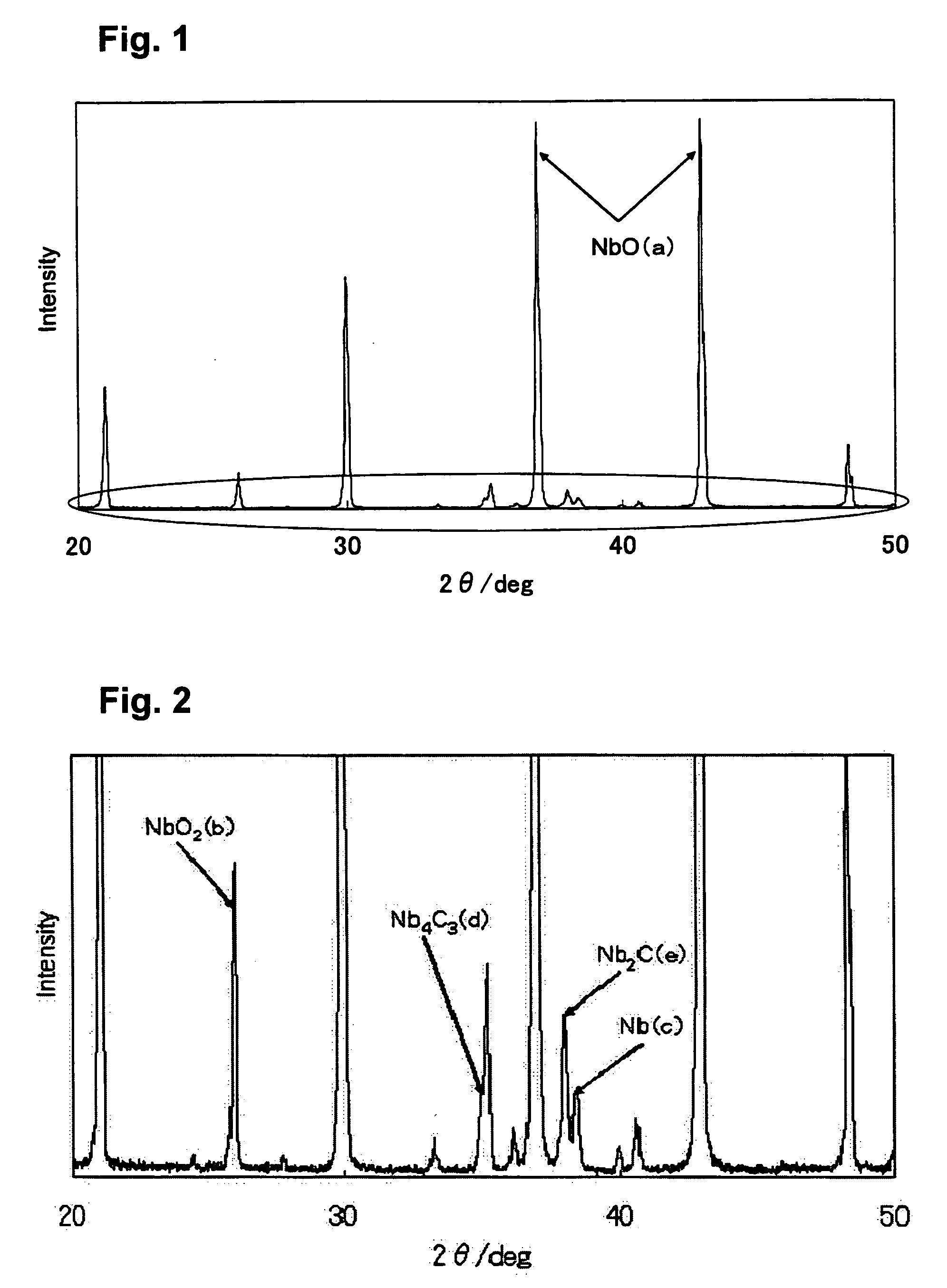
[0051] As can be seen from Table 3, further application of the reduction under a hydrogen atmosphere after each reduction treatment in the first and second steps provided such advantageous effects that unreacted niobium dioxide and remaining niobium carbides (Nb2C, Nb4C3) were eliminated to permit efficiently producing high-purity niobium monoxide.
[0052] A Series of Reactions: Description is made on a series of reduction treatments for producing niobium monoxide by reducing niobium pentoxide. Carbon was used both in the first step and the second step, and the obtained product was reduced under a hydrogen atmosphere.
[0053] In the first step, 0.96 kg of niobium pentoxide and 0.04 kg of carbon were dry mixed and placed in a carbon crucible disposed in a vacuum heating furnace. The temperature inside the vacuum heating furnace was increased at a rate of 20° C. / min, and the pressure reduction was started at 1400° C., and a reduction treatment was carried out at 1400° C. for 90 minutes. The pressure reduction inside the furnace was carried out down to 10 Pa. The sample subjected to the reduction treatment was taken out and subjected to X-ray analysis to carry out an identification and a quantitative determination of the constituent substances thereof. Consequently, 0.87 kg of niobium dioxide having a 100% purity was obtained.
[0054] Next, in the second step, 0.46 kg of the niobium dioxide thus obtained and 0.04 kg of carbon were used, the pressure reduction starting temperature and the reaction temperature were both set at 1500° C., and the reaction time was set at 10 minutes. The conditions other than those described above were the same as in the first step. The produced sample was found to have the following composition: niobium monoxide: 84%, metallic niobium (Nb): 2%, niobium dioxide: 8%, a niobium carbide (Nb2C): 4%, and a niobium carbide (Nb4C3): 2%.
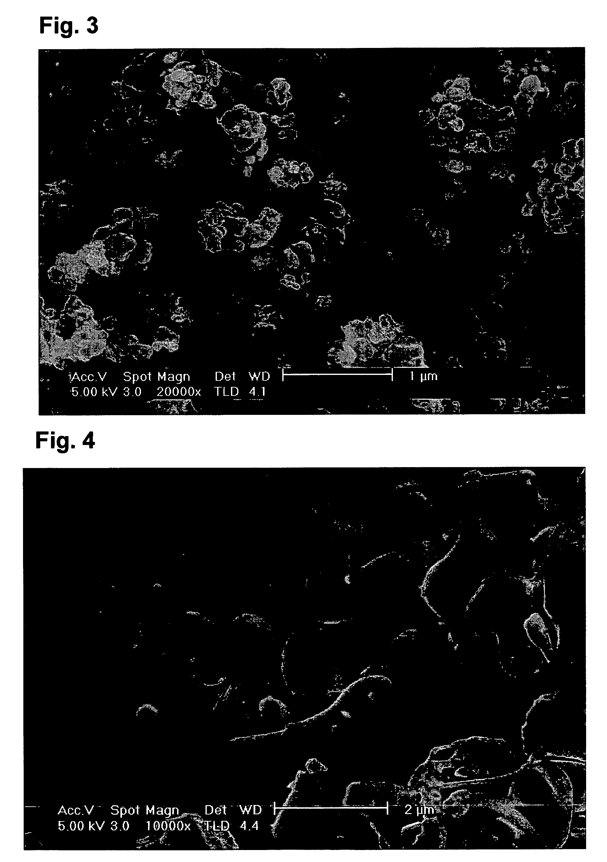
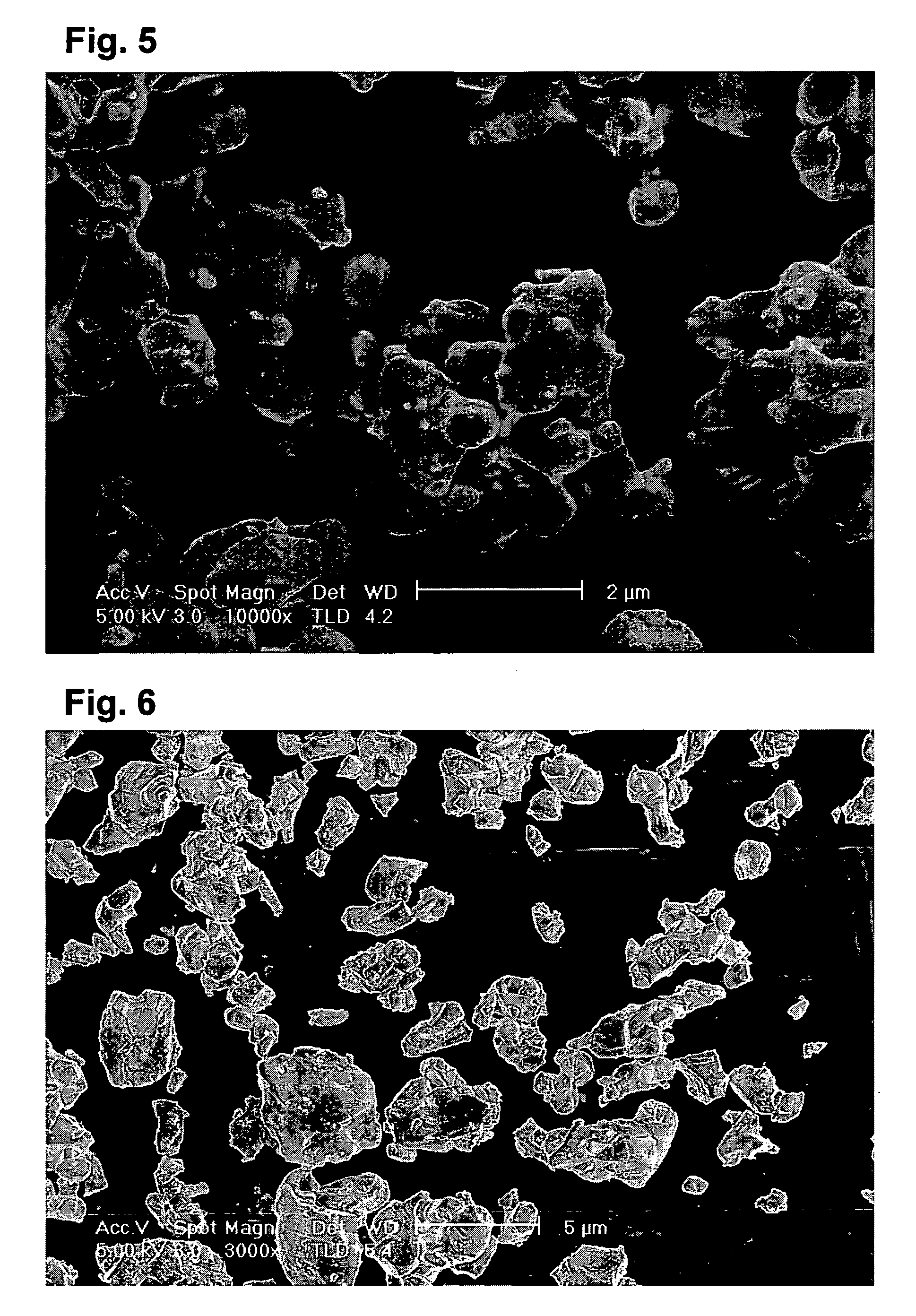
[0055] Finally, 0.1 kg of the sample obtained in the second step was subjected to a reduction treatment in a tubular furnace the interior of which was made to have a hydrogen atmosphere at the reaction temperature of 1400° C. for 4 hours. The obtained product was subjected to X-ray analysis to reveal that the product was NbO having a purity of 100%. The NbO as referred to herein includes the niobium oxides represented by the formula NbOx with the proviso that 0.7≦x≦1.1, and it should be understood that this is also the case in Examples presented below. The mean particle sizes D50 and the specific surface areas of the samples obtained are shown in Table 7 presented below.
[0056] From the above results, it was revealed that high-purity niobium monoxide was able to be produced by applying a series of production methods in which reduction treatments were carried out by using carbon in the first and second steps, and further, reduction was carried out under a hydrogen atmosphere.

Problems solved by technology

Recently, the amounts of niobium oxides used as raw materials for electronic components such as frequency filters and capacitors and as raw materials for targets in sputtering have been steeply growing.
Contamination of impurities such as alkali metals and heavy metals degrades the electric properties.
However, this method in which a niobium oxide is obtained by oxidizing niobium encounters difficulties in controlling the reaction and in obtaining fine particles because of grain growth.
This method for producing a low oxidation number niobium oxide by metal reduction cannot efficiently produce a high-purity niobium oxide, and hence cannot be said as a satisfactory method.

Method used


Image

  • Niobium oxide and method for producing the same
  • Niobium oxide and method for producing the same
  • Niobium oxide and method for producing the same

Examples


example 1

[0043] First Step: Description is made on a case where reduction was carried out by using carbon in the first step in which niobium pentoxide (Nb2O5) is subjected to dry reduction treatment into niobium dioxide (NbO2). As the raw materials, niobium pentoxide and a commercially available carbon (the particle size observed with SEM: 0.1 to 100 μm) were used. In a carbon crucible, 4.78 kg of niobium pentoxide and 0.22 kg of carbon were placed and mixed under stirring. The mixed raw material (5.00 kg) was placed in a carbon vessel disposed in a vacuum heating furnace.

[0044] The temperature inside the vacuum heating furnace was increased at a rate of 20 to 25° C. / min, and a pressure reduction was started at each of the temperatures of 1100° C., 1250° C. and 1400° C., and a reduction treatment was carried at 1400° C. for 30 minutes. The pressure reduction inside the furnace was carried out down to 10 Pa. Thereafter, each sample subjected to pressure reduction starting at the above descri...

example 2

[0052] A Series of Reactions: Description is made on a series of reduction treatments for producing niobium monoxide by reducing niobium pentoxide. Carbon was used both in the first step and the second step, and the obtained product was reduced under a hydrogen atmosphere.

[0053] In the first step, 0.96 kg of niobium pentoxide and 0.04 kg of carbon were dry mixed and placed in a carbon crucible disposed in a vacuum heating furnace. The temperature inside the vacuum heating furnace was increased at a rate of 20° C. / min, and the pressure reduction was started at 1400° C., and a reduction treatment was carried out at 1400° C. for 90 minutes. The pressure reduction inside the furnace was carried out down to 10 Pa. The sample subjected to the reduction treatment was taken out and subjected to X-ray analysis to carry out an identification and a quantitative determination of the constituent substances thereof. Consequently, 0.87 kg of niobium dioxide having a 100% purity was obtained.

[005...

example 3

[0058] Second Step: Description is made on a case where a niobium carbide was used as a reducing agent in the second step reaction in Example 1. The reduction was carried out under the same conditions as in Example 1 except that the reaction time was set at 90 minutes. It is to be noted that the temperature increase rate was set at 20° C. / min and the reduction temperature was set at 1600° C. for each of the pressure reduction starting temperatures. The NbO purities thus obtained are shown in Table 4.

TABLE 4BalancePressure reductionNbO purityNbNbO2Nb2CNb4C3starting temperature(%)(%)(%)(%)(%)14005303188150077120201600922510

[0059] As shown in Table 4, even when a niobium carbide was used as a reducing agent in the reduction reaction of the second step, niobium monoxide was obtained with purities approximately the same as those in the cases (Table 2) where carbon was used. In the balance, remaining niobium carbides (Nb2C, Nb4C3) as well as unreacted NbO2 were identified.


PUM

PropertyMeasurementUnit
specific surface areaaaaaaaaaaa
particle sizeaaaaaaaaaa
pressureaaaaaaaaaa

Abstract

An object of the present invention is to provide a niobium oxide that is suitable for application to capacitors, high in purity, large in specific surface area and small in particle size. The present invention also provides a method for producing such a high-purity niobium oxide. The present invention provides a niobium oxide that is a low oxidation number niobium oxide obtained from a high oxidation number niobium oxide, characterized in that the niobium oxide has a specific surface area (BET value) of 2.0 m2 / g to 50.0 m2 / g. The production method comprising dry reducing niobium pentoxide to produce niobium monoxide is characterized in that the reduction treatment is carried out stepwise in two steps. In the stepwise reduction, it is preferable that a carbon-containing reducing agent be used at least in any one of the two steps, and the temperature and the ambient pressure be maintained in a predetermined range in each of the steps.

Description

TECHNICAL FIELD [0001] The present invention relates to a niobium oxide large in specific surface area and small in particle size, and further relates to a method for producing the niobium oxide in a high purity. BACKGROUND ART [0002] Recently, the amounts of niobium oxides used as raw materials for electronic components such as frequency filters and capacitors and as raw materials for targets in sputtering have been steeply growing. In particular, among the niobium oxides, niobium monoxide (NbO) has been adopted as a new type raw material for capacitors, and such capacitors have come into wide use in a prevailing manner as capacitors that actualize large capacities in forms of small-sized chips and are provided with excellent electric stabilities and high reliabilities. [0003] In downsizing of niobium capacitors, it is essential to increase the electrostatic capacity of NbO to be dielectric material. The larger is the specific surface area of the niobium oxide as the raw material, ...

Claims


Application Information

Patent Timeline
Patent Type & Authority Applications(United States)
IPC IPC(8): C01G31/02
CPCC01G33/00C01P2002/72C01P2006/80C01P2006/12C01P2004/03
Inventor YONEDA, YOSHIHIROYASHIMA, ISAMUOGURA, SHUJI
Owner MITSUI MINING & SMELTING CO LTD
Learn More