Parabolic trough solar collector for fluid heating and photovoltaic cells

Inactive Publication Date: 2007-02-15
NIEDERMEYER WILLIAM P
View PDF10 Cites 42 Cited by
  • Summary
  • Abstract
  • Description
  • Claims
  • Application Information

AI Technical Summary

Benefits of technology

[0007] Generally, all solar collector power systems perform the same functions and require the same basic components including a parabolic reflector to focus solar rays on a heat absorbing conduit. Other components added to increase conversion efficiency include means to continuously pivot the reflector as the sun moves from east to west and the vacuumzed glass tube surrounding the heat

Problems solved by technology

Current designs have inherent cost and maintenance problems which together with the cyclic nature of the sun (including cloudy days) prevents solar power generating plants from producing cost effective power available around the clock.
Aside from cost and operating differences, the combined cycle plant still had C02 emission

Method used


Image

  • Parabolic trough solar collector for fluid heating and photovoltaic cells
  • Parabolic trough solar collector for fluid heating and photovoltaic cells
  • Parabolic trough solar collector for fluid heating and photovoltaic cells

Examples


Embodiment Construction

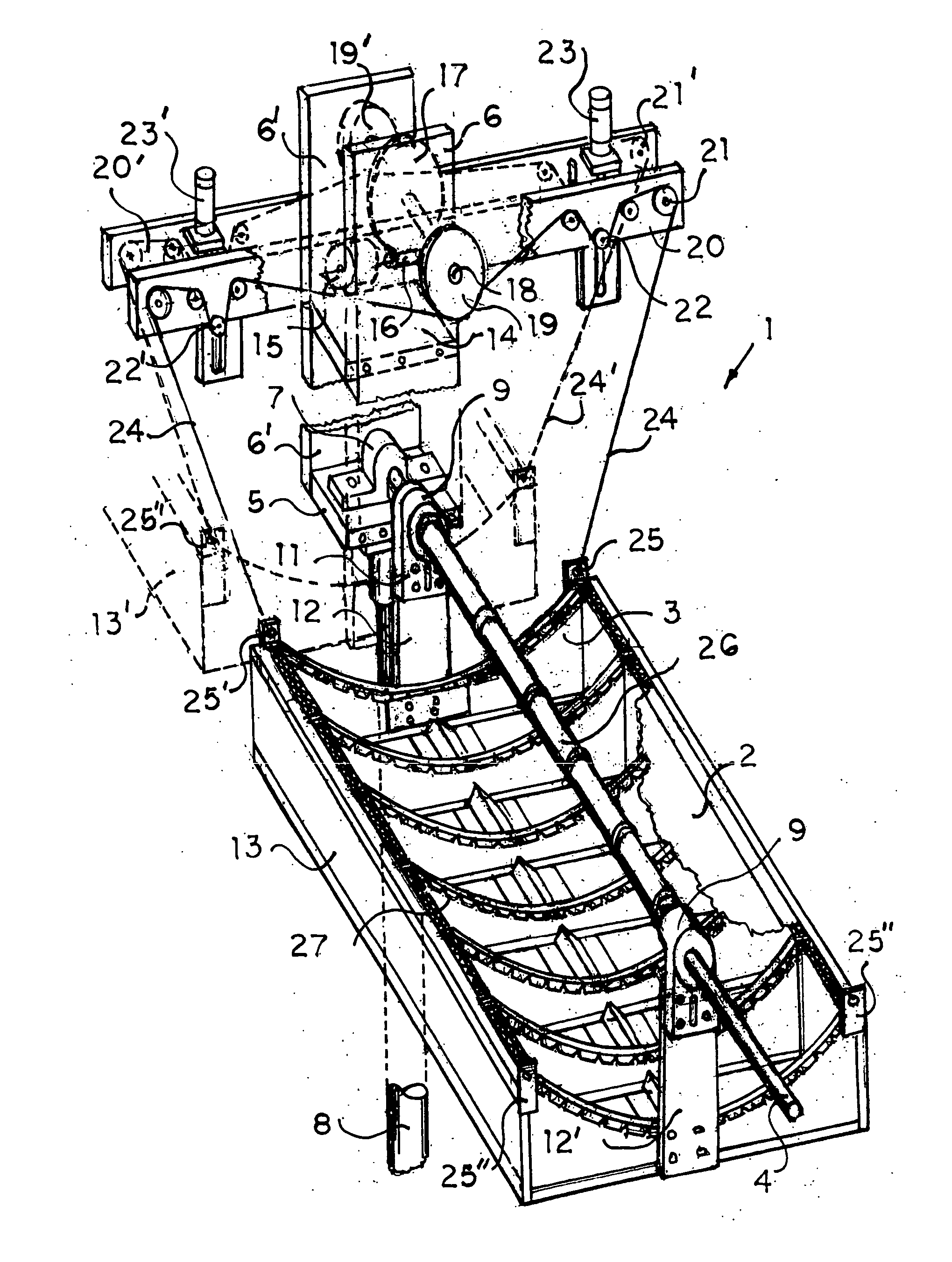
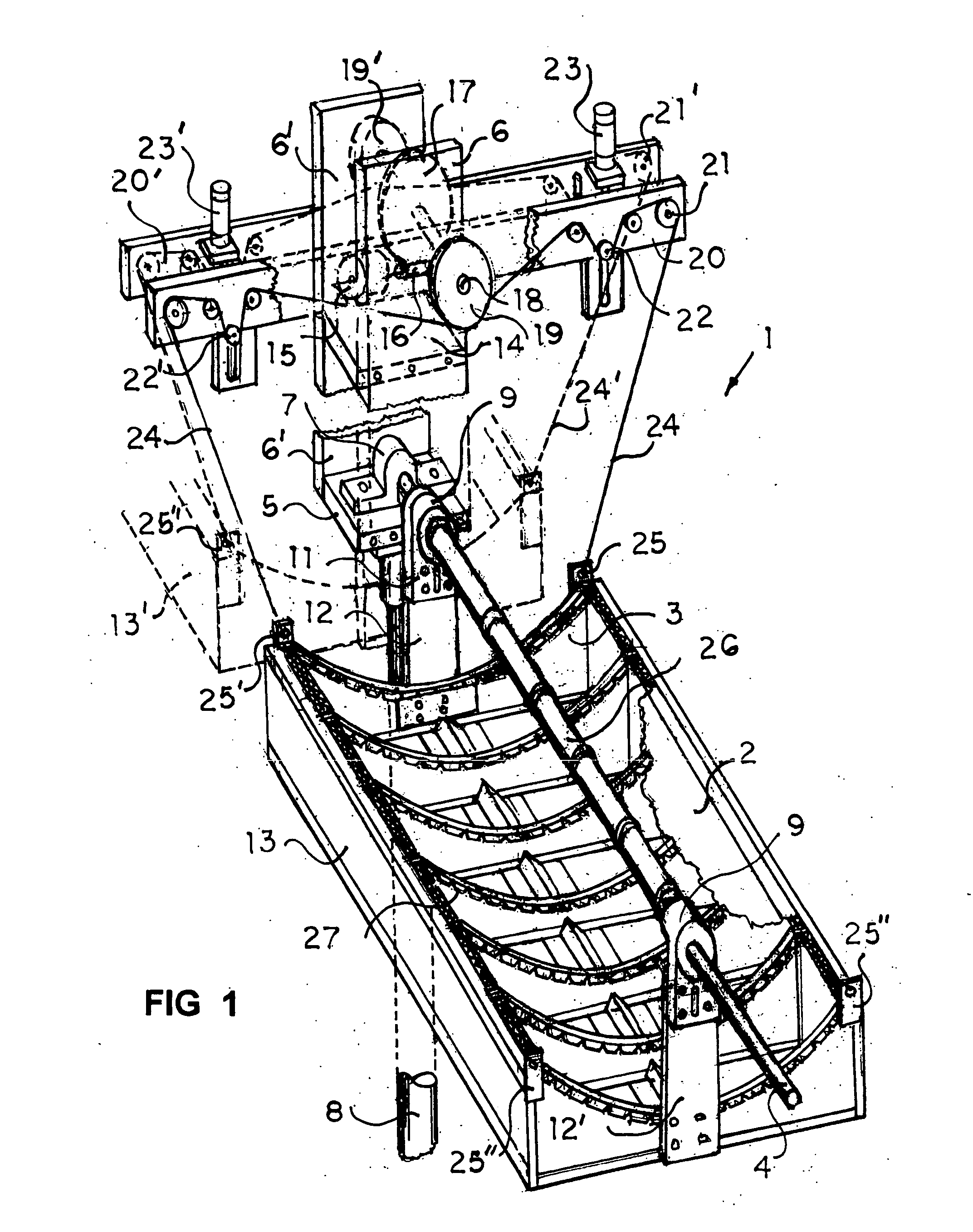
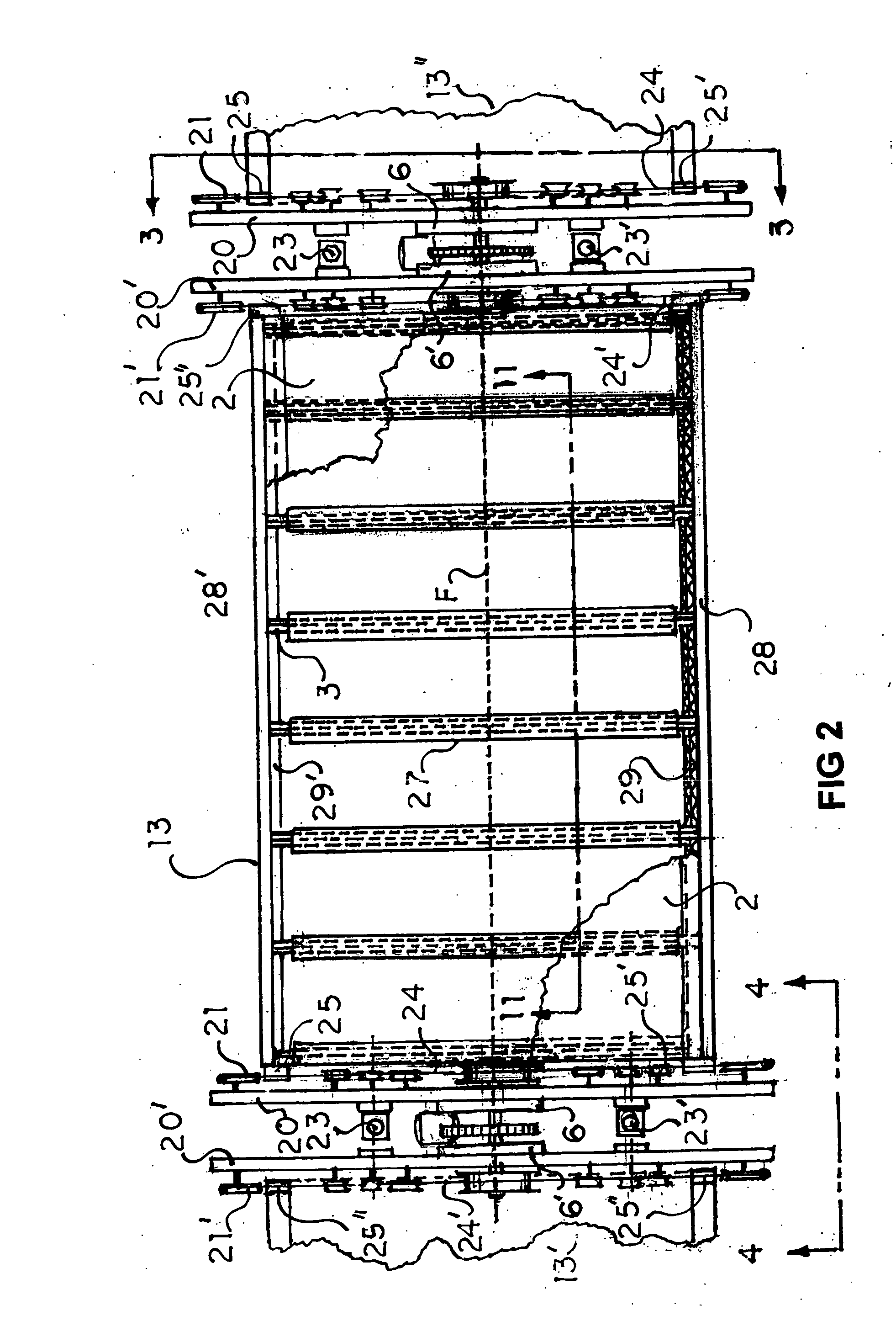
[0037] In FIG. 1, the parabolic trough concentrating collector 1 reflects solar reays from reflector surface 2 (portions cutaway) supported by a plurality of parabolic shaped transverse segments 3 with flexible strips 27 superposed and attached to side surfaces (as shown in FIGS. 1, 5, 6).

[0038] Reflected rays are directed to a focal line F co-incident with the centerline of conduit 4 which is secured to cross member 5 of vertically extended support 6 by clamp 7.

[0039] In FIG. 1, support extensions 6, 6′, and cross supports 5, 14 are attached to stationary post 8 and are fixed. Housing 9 with inside bushings 10 include a downwardly extending portion 11 for connection to and support of reflector support arms 12, 12′ which are attached to both ends of unitary reflector 13. The reflector 13, support arms 12, 12′ housing extensions 11, 11′ and housings 9, 9′ pivot from conduit 4,

[0040] In FIG. 1, the upper support extensions 6, 6′ include cross member 14 to support a programmable mot...


PUM


Abstract

A solar concentrating collector includes corrugated board parabolic support segments with flexible strips and side tabs over the cut edge to support a laminate with reflective coated film. The reflector assembly has supporting arms and pivots about a heat absorbing conduit secured to vertical extensions of adjacent stationary posts. Selected external surfaces are weatherproofed. The conduit includes vacuum insulators and means to isolate conduit from insulator expansion. Upper arms support pulleys and cable take-ups for continuous collector position changes. Cross members of the extended post secure the fixed conduit, and at a higher level, a programmable drive to rotate two cable capstans for cables that pivot two adjacent reflector assemblies. Other embodiments include triangular or square fluid conduits with planar surfaces for photovoltaic cells and a modified reflective surface to disperse solar rays into a band of reflected sunlight directed to photocell areas.

Description

BACKGROUND AND SUMMARY OF THE INVENTION [0001] The use of linear parabolic reflector troughs for concentrating solar rays on a heat collector pipe is well known. Prior collector systems for heating fluids to generate power depend from and use many of the same components as systems going back 40 or more years. [0002] Several current “state of the art” solar energy generating plants (SEGS) ranging from 30 to 320 megawatts are operating in the Mojave desert of California. The collectors include spaced parabolic truss supports extending transversely from about 6 to 18 ft wide. Collector systems heat fluids from 560 degrees to over 700 degrees F, and all use trusses extending outward from a pivoting central structure or tube, to support cast linear parabolic shaped mirrors to form the trough. [0003] Current parabolic mirror reflectors and trusses together with the attached absorber conduit are pivoted about a central structure or tube using hydraulic actuators and speed reduction gear bo...

Claims


Application Information

Patent Timeline
IPC IPC(8): F24J2/38F24S50/20
CPCF24J2/055F24J2/14F24J2/38F24J2/523F24J2/541Y10S126/906F24J2002/5468Y02E10/44Y02E10/45Y02E10/47F24J2/4636F24J2002/5458Y02E10/52H01L31/0547F24S40/80F24S2023/874F24S23/74F24S50/20F24S2030/133F24S30/425F24S25/10F24S10/45F24S2030/136Y02E10/40
Inventor NIEDERMEYER, WILLIAM PAUL
Owner NIEDERMEYER WILLIAM P
Why Eureka
Try Eureka