

Rectenna solar cell hybrid panel and hybrid photovoltaic power generation system
- Summary
- Abstract
- Description
- Claims
- Application Information
AI Technical Summary
Benefits of technology
Problems solved by technology
Method used
Image

Examples
embodiment 1
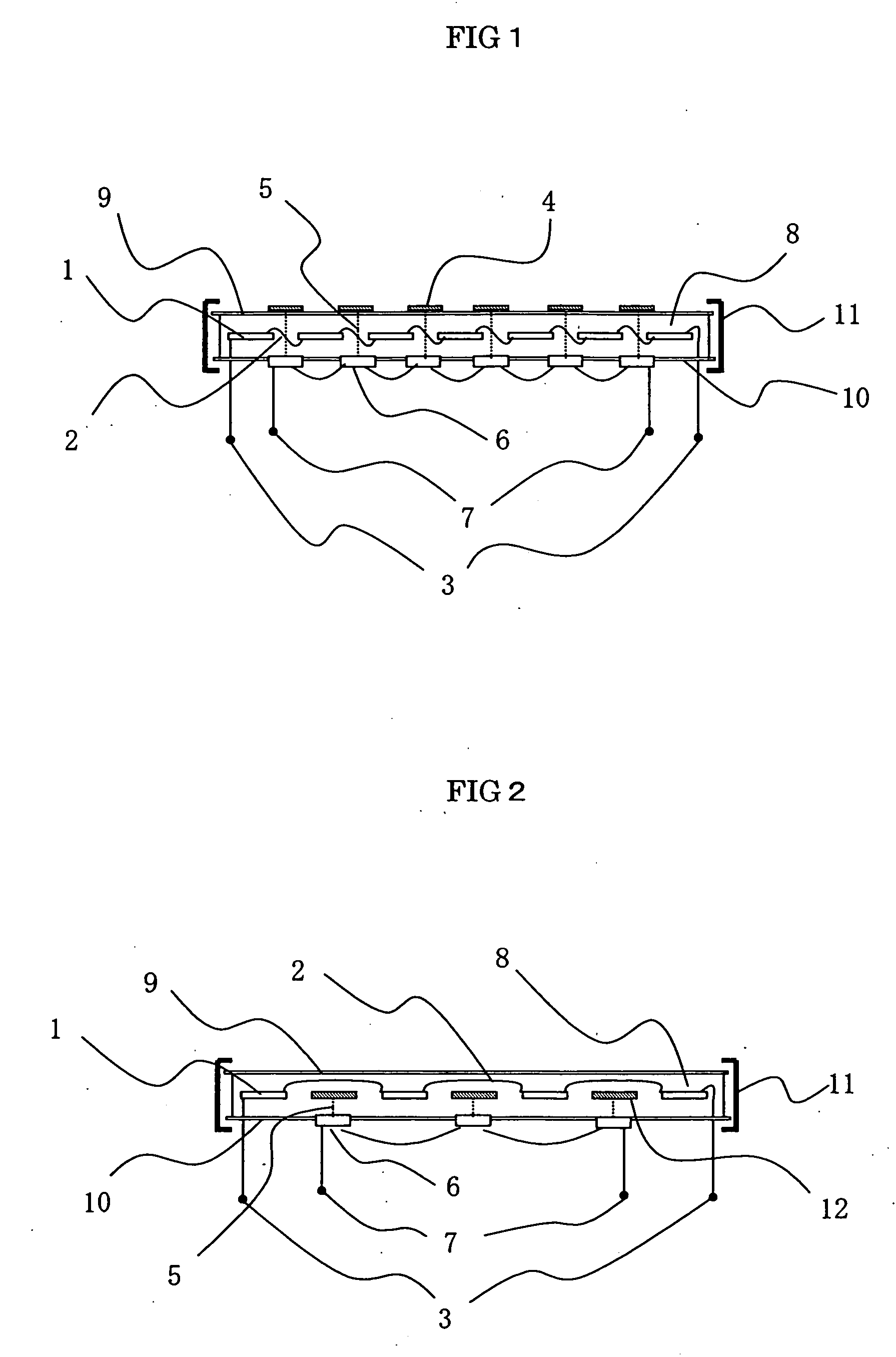
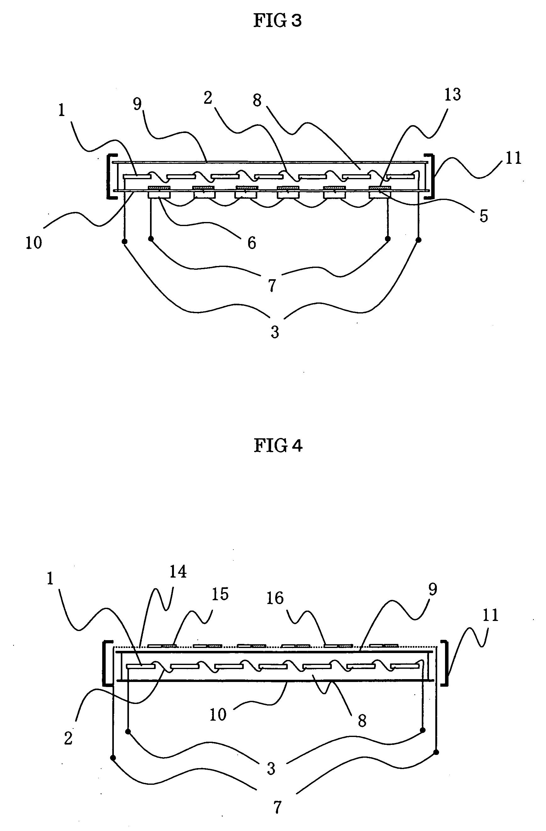
[0021] Rectenna solar-battery hybrid panels according to Embodiment 1 of the present invention are explained referring to FIG. 1-FIG. 4. Examples related to the different structures of the rectenna solar-battery hybrid panels are illustrated in FIG. 1-FIG. 4. In FIG. 1, numeral 1 denotes solar battery cells, and a plurality of cells is arranged in a rectenna solar-battery hybrid panel. Numeral 2 denotes inter connectors for connecting in series the solar battery cells; and numeral 3 denotes solar-battery output terminals for outputting generated dc electric power. Numeral 4 denotes microwave receiving antenna elements for receiving microwave power transmitted through space; numeral 5 denotes outputting lines of the microwave receiving antenna elements 4; numeral 6 denotes rectifying circuits for rectifying the received microwave power and converting the power into dc electric power; and numeral 7 denotes rectenna outputting terminals for outputting the dc electric power obtained fro...
embodiment 2
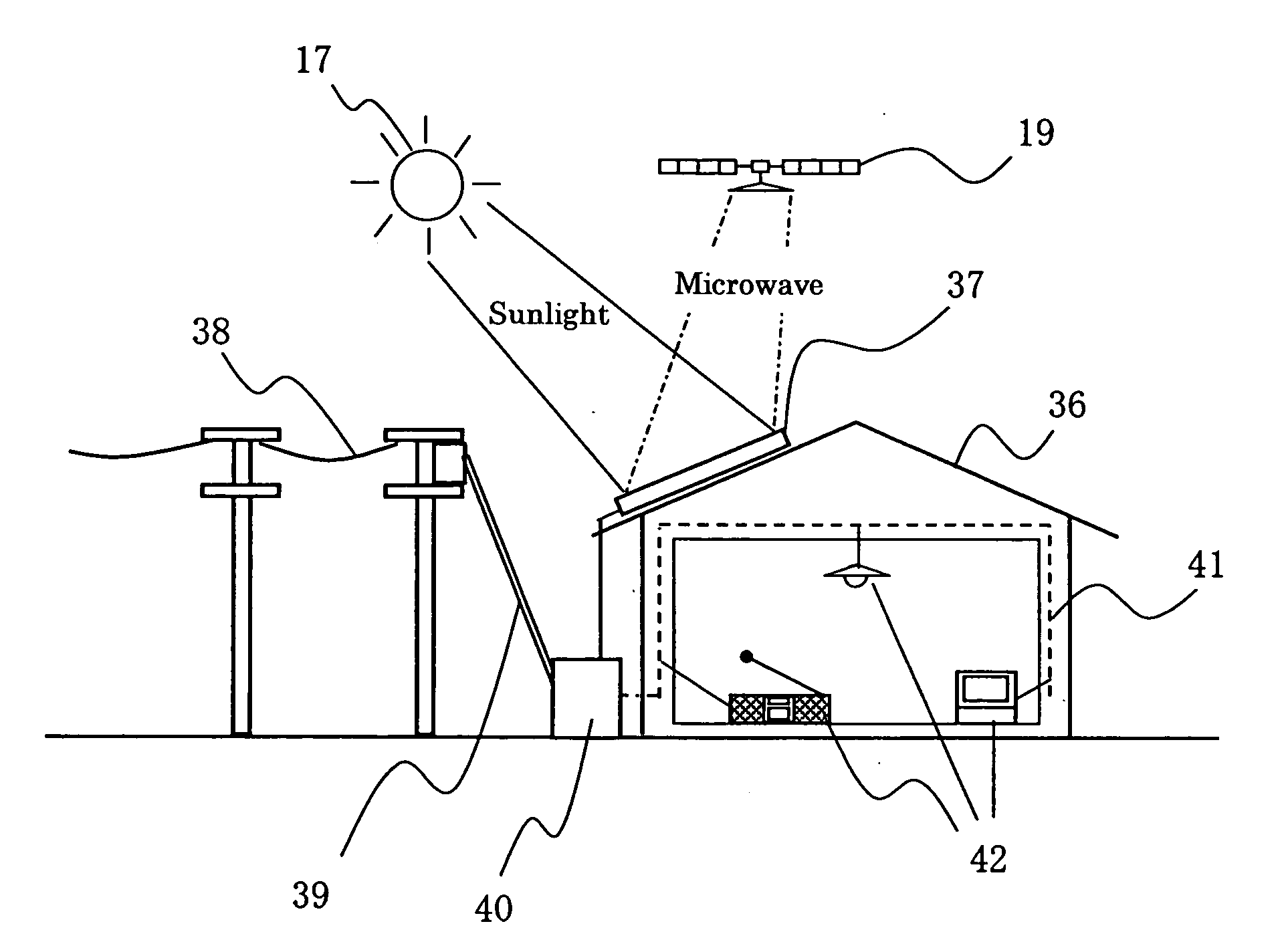
[0031] A hybrid solar photovoltaic generation system, applied to an artificial satellite, according to Embodiment 2 of the present invention is explained based on FIG. 5-Fig. 8. FIG. 5 is an outline view of the hybrid solar photovoltaic generation system, applied to the artificial satellite, according to Embodiment 2 of the present invention; FIG. 6 is a functional block diagram of the hybrid solar photovoltaic generation system according to Embodiment 2 of the present invention; FIG. 7 is a schematic view explaining an electric-power transmitting method in response to orbital positions of the artificial satellite in the hybrid solar photovoltaic generation system according to Embodiment 2 of the present invention; and FIG. 8 is a schematic view, when the artificial satellite and an electrical power generation satellite lie in the same orbit, explaining the positions of the satellites according to Embodiment 2 of the present invention.
[0032] In FIG. 6, numeral 17 denotes the sun to...
embodiment 3
[0041] A hybrid solar photovoltaic generation system according to Embodiment 3 of the present invention is explained using FIG. 9 and FIG. 10. FIG. 9 is an outline view illustrating a hybrid solar photovoltaic generation system according to Embodiment 3 of the present invention, and FIG. 10 is a configurational block diagram illustrating the hybrid solar photovoltaic generation system according to Embodiment 3 of the present invention. In FIG. 9, numeral 31 denotes rectenna solar-battery hybrid panels, which are the same as those in FIG. 1-FIG. 4 having been explained in Embodiment 1. Numeral 32 denotes a hybrid panel group in which a plurality of the rectenna solar-battery hybrid panels 31 is arranged. Numeral 33 denotes an electric-powercontrol equipment for controlling the hybrid panel group 32, combining dc electric power outputted from the hybrid panel group 32, and stabilizing the obtained electric power; and numeral 34 denotes transmission lines for supplying to an existing e...
PUM
 Abstract
Description
Claims
Application Information