

Exposure apparatus
a technology of exposure apparatus and exposure, which is applied in the field of exposure apparatus, can solve problems such as exposure failure, and achieve the effect of increasing exposure accuracy
- Summary
- Abstract
- Description
- Claims
- Application Information
AI Technical Summary
Benefits of technology
Problems solved by technology
Method used
Image

Examples
first embodiment
[0042] The schematic structure of an exposure apparatus according to a preferred embodiment of the present invention will be described first with reference to FIGS. 6 to 9. FIG. 6 is a front view of the exposure apparatus. FIG. 7 is a side view of the exposure apparatus. FIG. 8 is a plan view showing a lens barrel base 112 as a first structure on which, e.g., a projection unit (e.g., reticle stage (original stage) 107 and projection lens (projection optical system) 109) is mounted. FIG. 9 is a plan view showing a wafer stage base 113 as a second structure on which, e.g., a wafer stage (substrate stage) 111 is mounted.
[0043] The exposure apparatus according to the preferred embodiment of the present invention forms, using an exposure beam (a beam such as ultraviolet light, an excimer laser beam, EUV light (extreme ultraviolet light), X-rays, or an electron beam), a latent image pattern on a substrate coated with a photosensitive agent. The exposure apparatus which transfers the patt...
second embodiment
[0086] The second embodiment of the present invention may follow the first embodiment except for synchronous control of a lens barrel base 112 and wafer stage base 113.
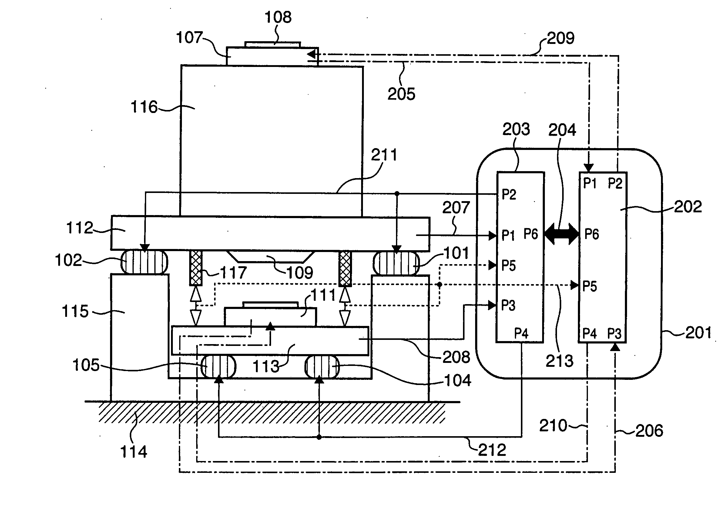
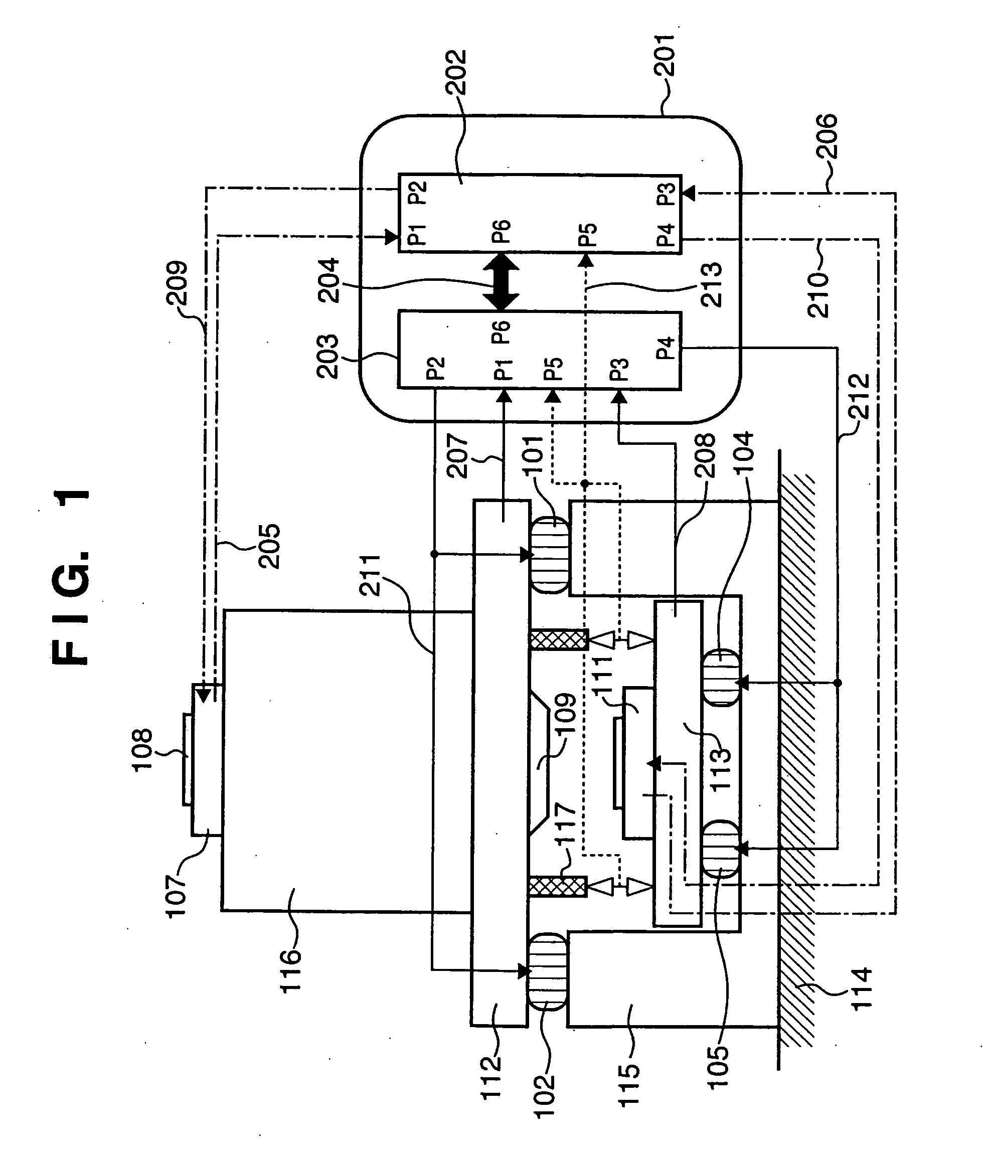
[0087] In the second embodiment, an anti-vibration supporting leg control operation unit 203 calculates the manipulated variables of anti-vibration supporting legs 101, 102, and 103 using control signals of anti-vibration supporting legs 104, 105, and 106. A stage control operation unit 202 sends a control signal 211 from its port P2 to an actuator (first actuator) of each of the anti-vibration supporting legs 101, 102, and 103, thereby synchronizing the lens barrel base 112 with the wafer stage base 113.
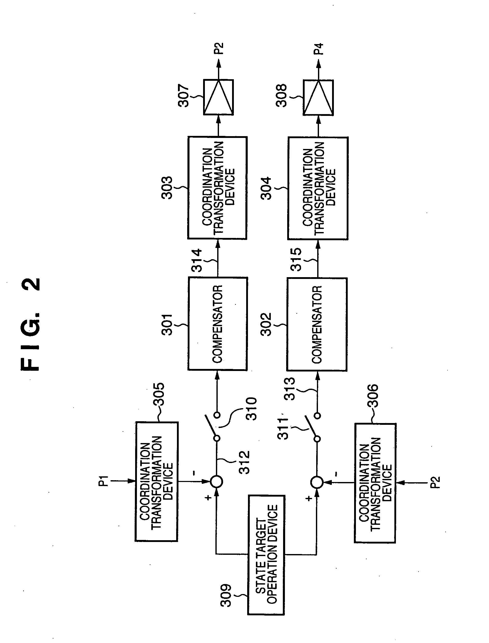
[0088] In the first arrangement example shown in FIG. 3, a switch 408 is set ON and a switch 409 is set OFF to cause a synchronous compensator 401 to generate, on the basis of a control signal 313, a control signal 416 serving as a correction signal of a control signal 312. The synchronous compensator 401 adds the c...
third embodiment
[0091] The third embodiment of the present invention may follow the first embodiment except for synchronous control of a lens barrel base 112 and wafer stage base 113.
[0092] In the third embodiment, an anti-vibration supporting leg control operation unit 203 calculates the manipulated variables of anti-vibration supporting legs 104, 105, and 106 using control signals of anti-vibration supporting legs 101, 102, and 103. An anti-vibration supporting leg control operation unit 203 sends a control signal 212 from its port P4 to an actuator (second actuator) of each of the anti-vibration supporting legs 104, 105, and 106, thereby synchronizing the lens barrel base 112 with the wafer stage base 113.
[0093] In the first arrangement example shown in FIG. 3, a switch 408 is set OFF and a switch 409 is set ON to cause a synchronous compensator 401 to generate, on the basis of a control signal 312, a control signal 417 serving as a correction signal of a control signal 313. The synchronous co...
PUM
 Abstract
Description
Claims
Application Information