Eureka AIR delivers breakthrough ideas for toughest innovation challenges, trusted by R&D personnel around the world.

Communications apparatus

Inactive Publication Date: 2007-02-15
GE OIL & GAS UK LTD
View PDF9 Cites 1 Cited by
  • Summary
  • Abstract
  • Description
  • Claims
  • Application Information

AI Technical Summary

Benefits of technology

[0007] The low power consumption of the EDFA allows its electric power supply to be fed down the umbilical via small, typically 16 mm2, wires which are run alongside the fibre-optic bundles, replacing some of the ‘fillers’ used in the cable construction whilst avoiding compromising the main power feeds. Typically, power is fed at 500 V DC to minimize voltage drop down the umbilical and is then dropped to a voltage suitable for the EDFAs by small DC / DC converters.
[0009] This invention overcomes the problems outlined above and enables reliable fibre-optic communications for control and monitoring of subsea wells at distances in excess of 600 Km between the control centre and the well, whilst maintaining compatibility with cable-laying vessels during deployment of the umbilical.

Problems solved by technology

Installations are now planned at distances in the order of 600 Km from the shore, which presents new problems for the supply of power and communications via an umbilical.
Fibre optic communication is limited, using relatively cheap laser diodes to about 200 Km with current technology, although research organizations are proposing to stretch this to about 300 Km with further development of optical devices.
Above this distance it is necessary and traditional to use either high power gas lasers or electronic repeaters (modems), both of which are expensive and power-hungry solutions.
The manufacture and deployment of a continuous length of some 600 Km of umbilical is accepted by subsea well operators as impractical and thus splicing of the umbilical is a necessity.
The problem with electronic repeaters is that they are not only power-thirsty but bulky.

Method used


Image

  • Communications apparatus
  • Communications apparatus
  • Communications apparatus

Examples


Embodiment Construction

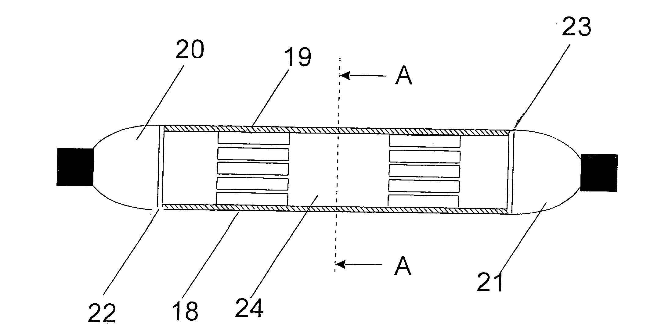
[0037] Looking firstly at FIG. 1, an EDFA is provided at a fibre-optic cable 1, which has a relatively small part of its length 2 doped with Erbium. This part is pumped by a laser diode 3 which is mounted on and cooled by a Peltier device 4. The laser diode and Peltier currents are controlled by an electronic module 5 which is supplied with electric power via a DC / DC converter 6, fed from a high voltage supply 7.

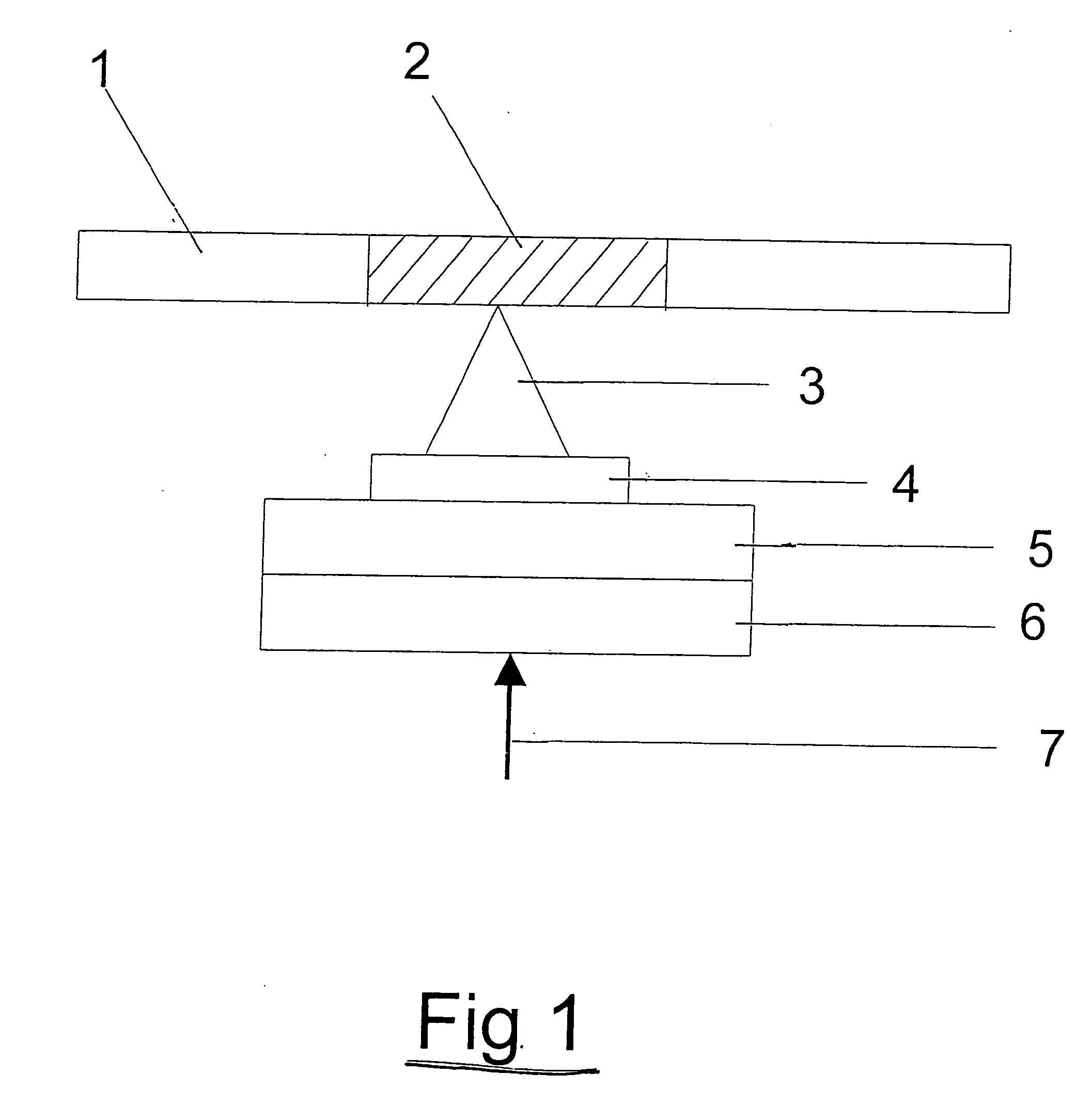
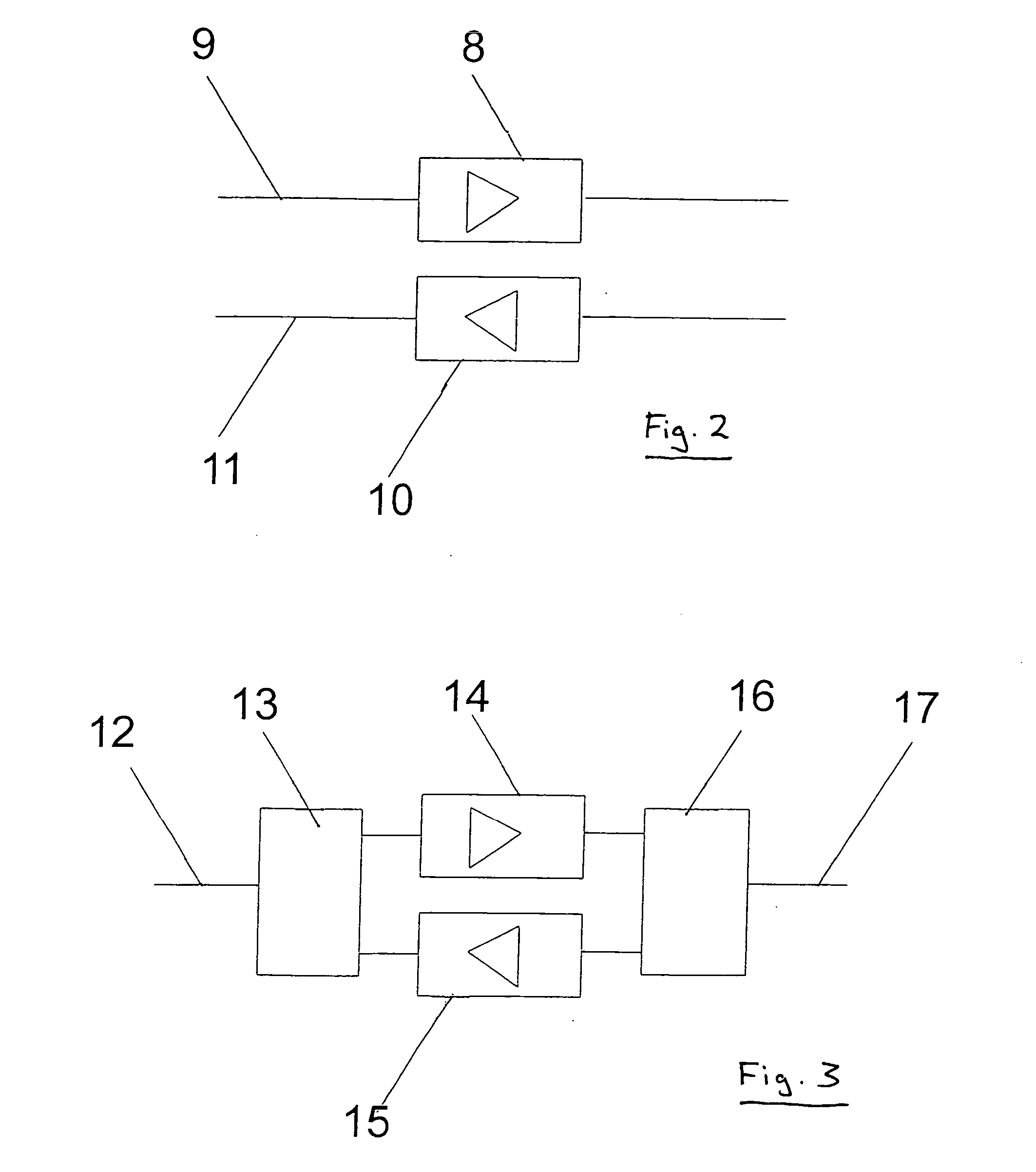
[0038] EDFAs are not full duplex devices and can only handle communication in one direction. FIG. 2 shows a first arrangement to cater for the single-way communication limitation of the EDFAs but still provide full duplex operation. An EDFA 8, inserted into a fibre-optic cable 9 provides single one-way communication left to right in the figure. A second EDFA 10 is inserted in a second fibre-optic cable 11, providing communication right to left in the figure. FIG. 3 shows an alternative arrangement, in which a fibre-optic cable 12 is split by an optical splitter 13, to feed ...


PUM


Abstract

A communications device for underwater use includes an umbilical which contains a length of optical fibre for carrying communications signals. The umbilical also has an optical amplifier provided along said length for boosting the intensity of said signals, and an electrical power line for supplying power to the amplifier. Additionally, the umbilical has a connection device for splicing two cables, each cable carrying a length of optical fibre for carrying communications signals. The connection device has a housing having two ports for accepting respective cables, and an optical amplifier for boosting the intensity of said signals, the amplifier being supplied with power by an electrical power line carried by at least one of the cables.

Description

FIELD OF THE INVENTION [0001] This invention relates to a communications apparatus for controlling and / or monitoring an underwater hydrocarbon well, a connection device for joining two cables and a method for enabling communication with an underwater well facility. BACKGROUND OF THE INVENTION [0002] Control of offshore fluid extraction wells is typically effected from the shore via an umbilical. The umbilical typically carries hydraulic and electrical power, and communication for control and monitoring of the well. Earlier installations were relatively close to the shore and thus communication with the well complex could be achieved with conventional wires and modems. Later installations tended to be at greater distances from the shore, such as 100 Km, and benefited from the application of fibre optic methods of communication. Installations are now planned at distances in the order of 600 Km from the shore, which presents new problems for the supply of power and communications via a...

Claims


Application Information

Patent Timeline
IPC IPC(8): H04B10/02E21B47/12H04B10/80
CPCH04B10/808E21B47/123E21B47/135G02B6/3817
Inventor BAGGS, CHRISTOPHER DAVIDNAWAZ, MOHAMMED
Owner GE OIL & GAS UK LTD
Why Eureka
Eureka Blog
Learn More