
High-frequency treatment tool

a high-frequency treatment and tool technology, applied in the field of high-frequency treatment tools, can solve the problems of inability to confirm the diseased portion, the front end of the needle-like knife cannot be captured in the observation field of the endoscope, and the inability to secure the safety of treatment, so as to achieve safe and rapid treatment and simple structure.

Active Publication Date: 2007-02-15
FUJIFILM CORP
View PDF4 Cites 27 Cited by
  • Summary
  • Abstract
  • Description
  • Claims
  • Application Information

AI Technical Summary

Benefits of technology

[0014] The invention was developed in view of these circumstances, and an object thereof is to realize safe and efficient treatment by using a high-frequency treatment tool that uses a needle-like knife and is simple in structure.
[0022] As in the above, the hard cylinder has an extremely simple cylindrical shape, and the hard cylinder can be easily formed of, for example, a ceramic material. However, it is not always necessary to form the hard cylinder of a ceramic material, and it maybe formed of a synthetic resin or the like excellent in heat resistance. On the other hand, the high-frequency knife is formed of a conductive member, for which the rod-like electrode and the blade portions and stopper surfaces are integrally formed of a metal material that is easy to process.
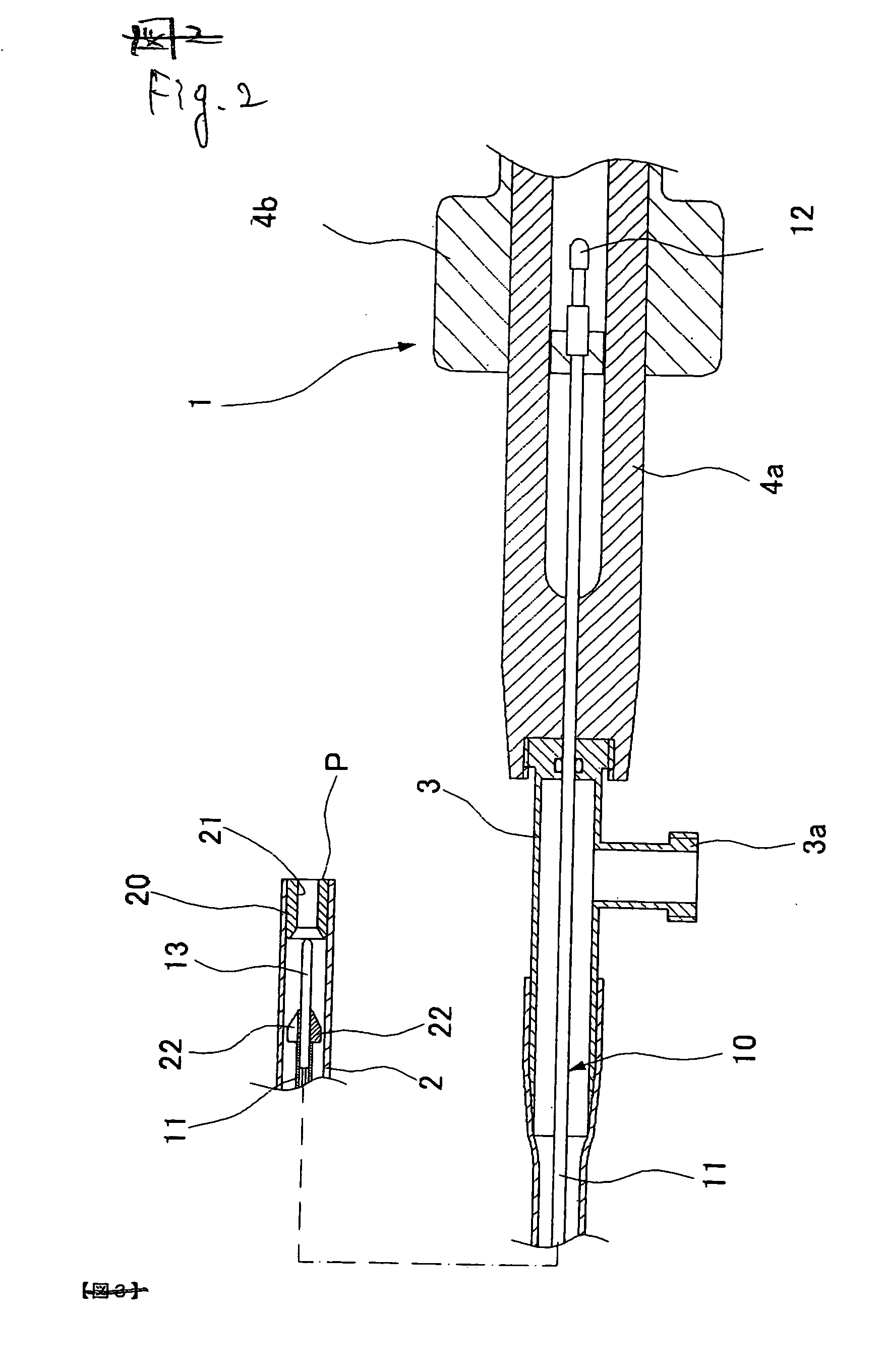
[0023] By operating the flexible cord by pushing and pulling in the flexible sheath, this can be displaced into a condition where the high-frequency knife is stored inside the flexible sheath and a condition where the same is protruded from the front end of the flexible sheath. When the high-frequency knife has protruded by a predetermined amount, since the stopper surfaces abut against the base-end face of the hard cylinder, this position equals the maximum protruding position of the high-frequency knife, and a treatment such as incision is executed in this condition. Accordingly, the protrusion length of the rod-like electrode of the high-frequency knife at the maximum protruding position is set so as to be optimal according to a treating site. For example, when a mucosal stripping treatment is conducted, the protrusion length of the rod-like electrode is longer than the thickness dimension of the mucosa and is shorter than the total thickness dimension of the mucosa and submucosal layer. Thereby, safety is secured when the treatment is conducted and it can be prevented from leaving the diseased mucosa unremoved.
[0025] When the high-frequency knife has been drawn into the flexible sheath, this is sometimes positioned further at the base-end side than the hard cylinder. In this case, in order to lead the front end of the rod-like electrode smoothly and reliably to the through-hole of the hard cylinder, it is sufficient to mount a lead-in member at a position on the base-end side of the hard cylinder. The lead-in member is a ring-like member, whose end face on the base-end side is inclined toward the front-end side. The lead-in member has an inside diameter that allows inserting the high-frequency knife there through. Since the lead-in member is not exposed outside, it is not always necessary to form the same of an electrical insulating member, and it can be easily formed of a plastic material, a metal material, or the like.
[0027] By employing the above structure, effects are provided such that it becomes possible, by mounting a hard cylinder with a simple structure in a flexible sheath, to regulate the protrusion amount of a high-frequency knife formed of a rod-like electrode, and when a treatment such as incision is carried out, to secure safety of the high-frequency knife so as to enable a safe and swift treatment, and to supply and discharge a fluid during the treatment.BRIEF DESCRIPTION OF THE DRAWINGS

Problems solved by technology

When the needle-like knife is used, the needle-like knife is positioned ahead of the flexible sheath and punctures the mucous membrane, so that in some cases of performing the treatment, the front end of the needle-like knife cannot be captured in the observation field of the endoscope.
Therefore, unless the sticking-out length and sticking-out direction of the needle-like knife from the flexible sheath are accurately controlled, the safety of the treatment cannot be secured.
During the treatment to excise the diseased portion by using the above-described electrode member, bleeding occurs in some cases, and this may make it impossible to confirm the diseased portion.
In the method according to JP-A-2004-313537, the operations for catching mucous membrane or submucosal layer by the hook knife forming the electrode member, drawing it into the treatment tool insertion channel, and then supplying the hook knife with a current to cauterize and cut the tissue, and leading-out the hook knife again from the treatment tool insertion channel, are repeated, so that the operations become complicated and difficult, and operation efficiency cannot be obtained.
Therefore, it takes a long time to perform the treatment to remove the diseased mucous membrane, and accordingly, the pain of the examinee and the burden on the operator may increase.
The hook portion is always exposed to the outside, and for example, during insertion into the treatment tool insertion channel, if the electrode member is supplied with a current by mistake, it may damage the channel inner wall.
Herein, the electrical insulating member must be made of a material with excellent heat resistance, and therefore, desirably, it is made of ceramic, however, it is difficult to form the through hole having the above-described shape in this ceramic.

Method used


Image

  • High-frequency treatment tool
  • High-frequency treatment tool
  • High-frequency treatment tool

Examples


first embodiment

[0051] [First Embodiment]

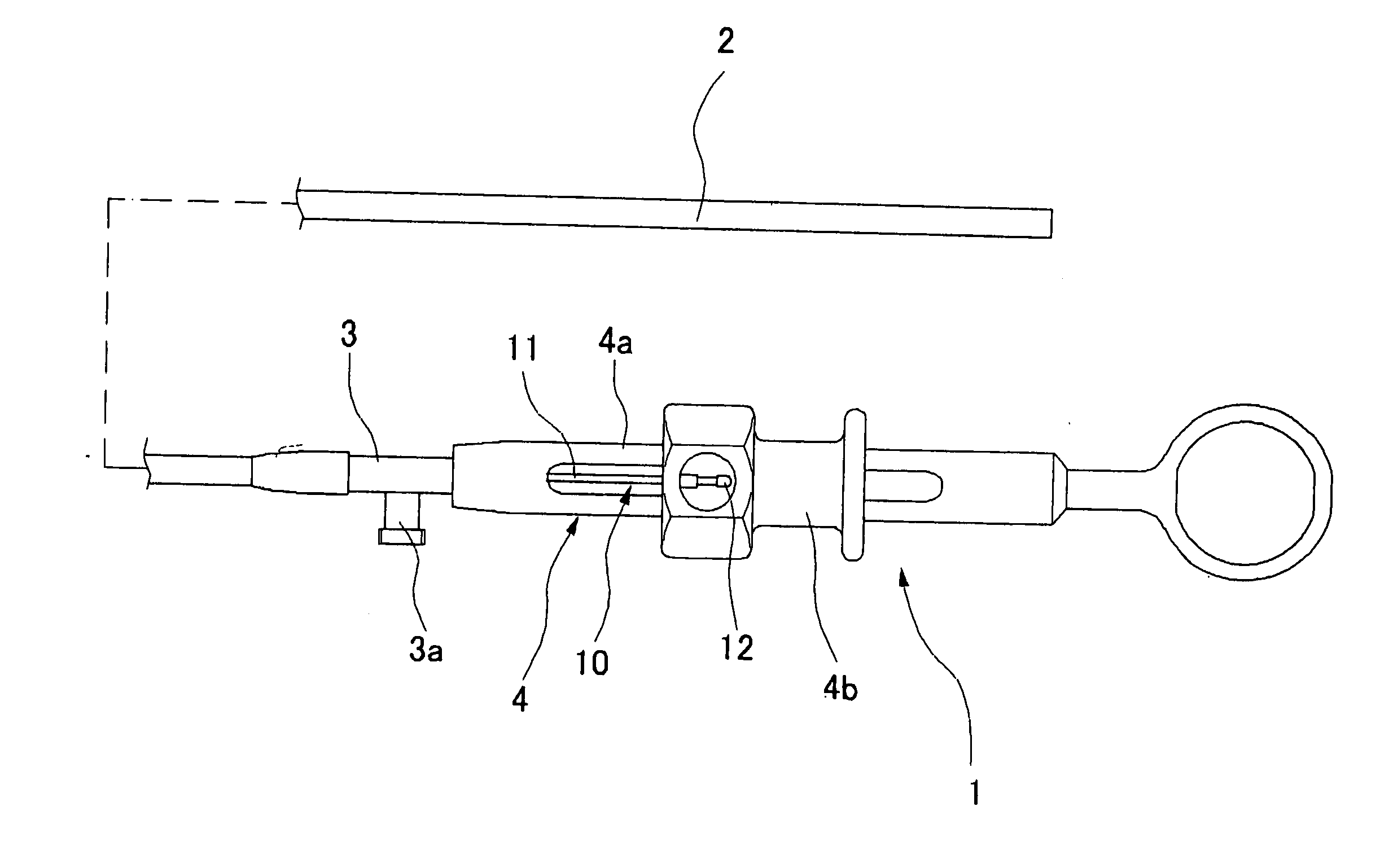
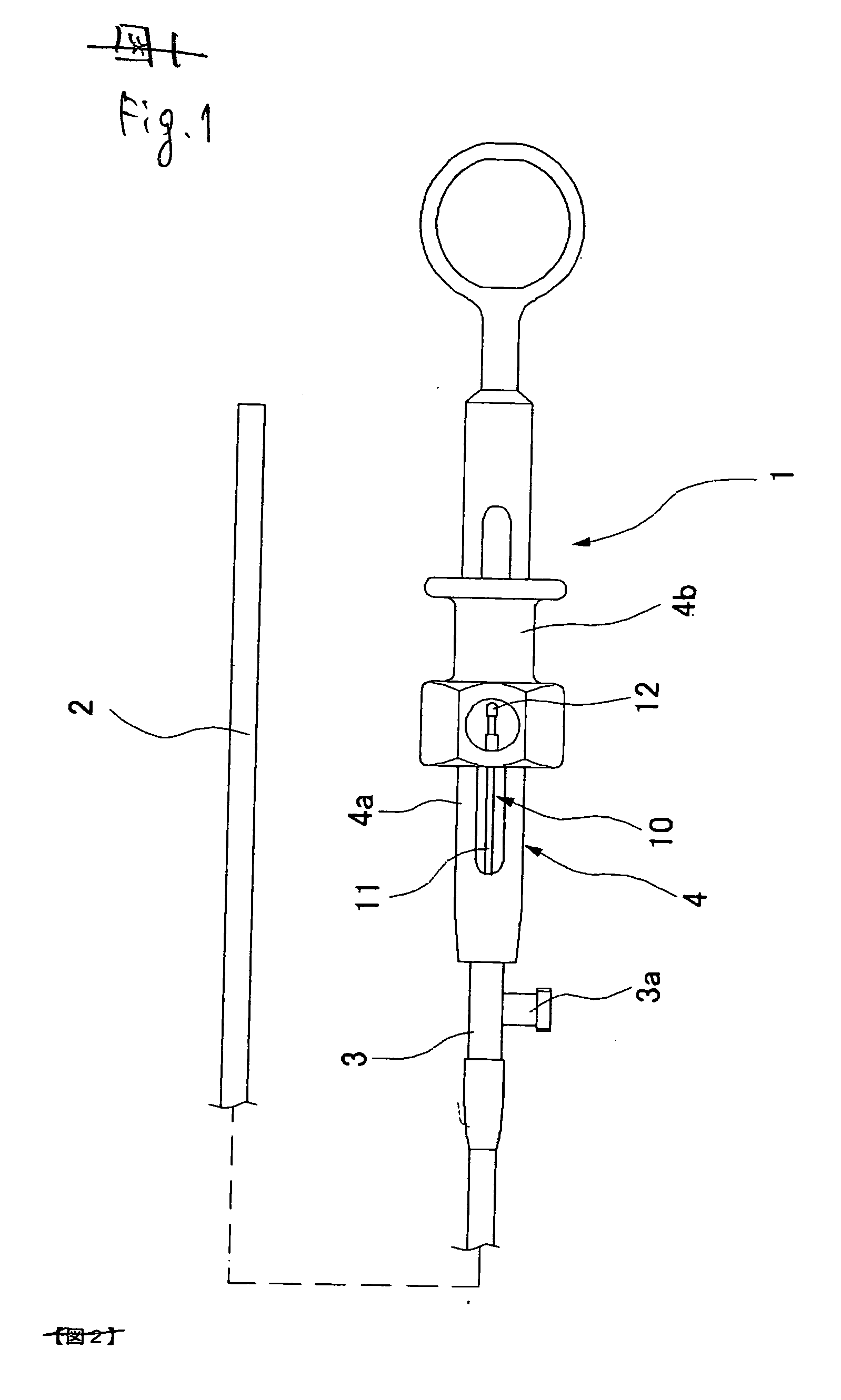
[0052] Hereinafter, the first embodiment of the invention will be explained. FIG. 3 and FIG. 4 show the section of the front end portion of the high-frequency treatment tool in actuating states different from each other. As clearly seen in FIG. 3, the flexible cord 11 is formed by inserting, for example, the outer circumference of a lead wire 11a into an insulating coating 11b, and has flexibility in at least the bending direction. The base end of the lead wire 11a of the flexible cord 11 sticks out by a predetermined length from the portion joined to the slider 4b to form a contact portion 12. This contact portion 12 is connected to an unillustrated high-frequency power supply apparatus in a disconnectable manner.

[0053] The flexible cord 11 forming the treatment tool body 10 is extended to the inside of the flexible sheath 2 through the inside of the connecting pipe 3 from the portion attached to the slider 4b. The needle-like knife 13 is provided so as to...

second embodiment

[0060] [Second Embodiment]

[0061] Hereinafter, the second embodiment of the invention will be explained.

[0062] As shown in FIG. 8, the flexible code 11 includes a conductive line portion 11a formed of a flexible member whose outer circumferential portion has been applied with insulating coating, a base-end portion of the conductive line portion 11a is provided while being protruded by a predetermined length from a coupling portion to the slider 4b, a contact portion 12 is provided on the base-end portion, and the contact portion 12 is attachably and detachably connected to an unillustrated high-frequency power unit. As shown in FIG. 9, the front end of the conductive line portion 11a is coupled with a hollow wire 11b. The hollow wire 11b is formed of a conductive member having flexibility in a bending direction, and an outer circumferential surface thereof is coated with an insulating member. Therefore, the conductive line portion 11a is electrically conductive with the hollow wire ...


PUM


Abstract

A high-frequency treatment tool comprising: a flexible sheath to be inserted into a treatment tool insertion channel of an endoscope; a treatment tool body provided inside the flexible sheath and comprising: a flexible cord; and a high-frequency knife to which a high-frequency current is applied, formed to the front end of the flexible cord; and a hard cylinder having an electrical insulating property, inserted and fixed inside the flexible sheath, wherein the high-frequency knife comprises blade portions radially provided in its axial direction, each of the blade portions including an engaging part, and wherein, when the high-frequency knife is made to stick out from the hard cylinder, engaging parts of the blade portions abut against a rear end portion of the hard cylinder so that: the high-frequency knife is engaged with the hard cylinder; and communicating channels that communicate an inside and an outside of the flexible sheath are formed between the blade portions adjacent to each other.

Description

BACKGROUND OF THE INVENTION [0001] 1. Field of the Invention [0002] The present invention relates to a high-frequency treatment tool that is inserted into a treatment tool insertion channel of an endoscope and used for performing a treatment such as incision of a diseased mucous membrane. [0003] 2. Description of the Related Art [0004] When a diseased portion such as a tumor is found on the mucous membrane on a body cavity inner wall of the gullet, stomach, duodenum, or colon by endoscopic inspection, a treatment is performed to excise the portion of the diseased mucous membrane by using a high-frequency treatment tool. In this case, to secure safety of the treatment, the treatment is performed under observation through an endoscope, and the high-frequency treatment tool used for the treatment is inserted into the treatment tool insertion channel of the endoscope and guided to the portion to be treated. Herein, on the body cavity inner wall, the submucosal layer exists below the muc...

Claims


Application Information

Patent Timeline
Patent Type & Authority Applications(United States)
IPC IPC(8): A61B18/14
CPCA61B18/1402A61B18/1477A61B18/1492A61B2218/002A61B2018/1425A61B2018/1475A61B2019/304A61B2018/00482A61B2090/034
Inventor MACHIYA, MAMORUOYATSU, MASAYUKIAKIBA, HARUOIYAMA, SHOZOKANAKI, ATSUSHIAKAHANE, HIDEFUMI
Owner FUJIFILM CORP
Learn More