Mopping system and method of use

a technology of mopping head and mop head, which is applied in the field of mopping, can solve the problems of affecting the cleaning effect of mop head, and accumulating significant amount of water fouling material, etc., and achieves the effects of convenient application, quick and thorough cleaning and drying, and preventing contamination

Inactive Publication Date: 2007-02-22
SPIN MOP
View PDF7 Cites 27 Cited by
  • Summary
  • Abstract
  • Description
  • Claims
  • Application Information

AI Technical Summary

Benefits of technology

[0012] The mop assembly may include a lever means for selectively detaching the mop head from the handle. As such, the user does not have to bend down to engage the mop head with the mop head spinning means of the bucket assembly. Alternately, the mop head may be rotationally fixed to the elongated handle such that it can only spin around its rotational axis when engaged with the mop head spinning means.
[0013] The present invention is an improved mopping system that allows for convenient, quick and thorough cleaning and drying of a mop head. The present device allows clean water or a cleaning solution to be applied to a mop head easily, and prevents contamination between a clean water solution and a fouled-water container. Moreover, the present invention provides for easy sterilization of the mop head and the fouled water to prevent biological growth therein, and allows for easy, hands-free emptying of the fouled water. The invention is self-contained, easily portable from location to location as needed, and greatly improve the sanitary conditions of floors mopped therewith, substantially eliminating re-contamination thereof by a fouled mop head. Other features and advantages of the present invention will become apparent from the following more detailed description, taken in conjunction with the accompanying drawings, which illustrate, by way of example, the principles of the invention.

Problems solved by technology

However, at this point not all of the contaminants have been removed from the mop in the wringing process, and a significant amount of water fouling material is deposited into the clean water compartment.
In prior art mop buckets with only a single bucket compartment, the problem is compounded by the fact that dirt that is removed from the mop and wrung-out into the water compartment can be immediately picked-up again by the mop and re-applied to the floor surface that is being mopped.
Mopping with such prior art buckets quickly becomes an exercise in futility, as applying contaminated water to a contaminated floor does little to clean the floor.
Further, often the employees who are charged with mopping the floor are indifferent as to whether or not the process actually cleans the floor, the result being poor sanitary conditions throughout the establishment.
The force of the strands against the perforations of the basket can actually block water and dirt flow out of the mop strands.
Thus, while such a device is better at removing dirt and water from the mop, it is by no means optimal at such.
A further drawback to the Trisolini devices is that they are somewhat tall in their profile, and are therefore more difficult to store and maneuver.
Further, such prior art mop assemblies are heavy due to the hollow cleaning fluid chamber therein, and as such a person mopping with such a device can quickly become exhausted.
The main drawback with such a device is, again, the mop of such a device is heavy and quickly becomes exhausting to use.
The motor of such a device, as well as the batteries to power it, are extra weight that the user is forced to propel around the floor while mopping.
Further, such prior art devices do not include intelligent controlling means for shutting-off the sterilizing device if the bucket is empty or is not being used.
Thus, one can easily inadvertently leave such a device activated, both wasting energy and possibly over-exposing the mop and surrounding areas to UV light and ozone.
Such a needed device would allow clean water or a cleaning solution to be applied to the mop head easily, and would not allow cross-contamination between the clean water solution and the fouled-water container.

Method used


Image

  • Mopping system and method of use
  • Mopping system and method of use
  • Mopping system and method of use

Examples


Embodiment Construction

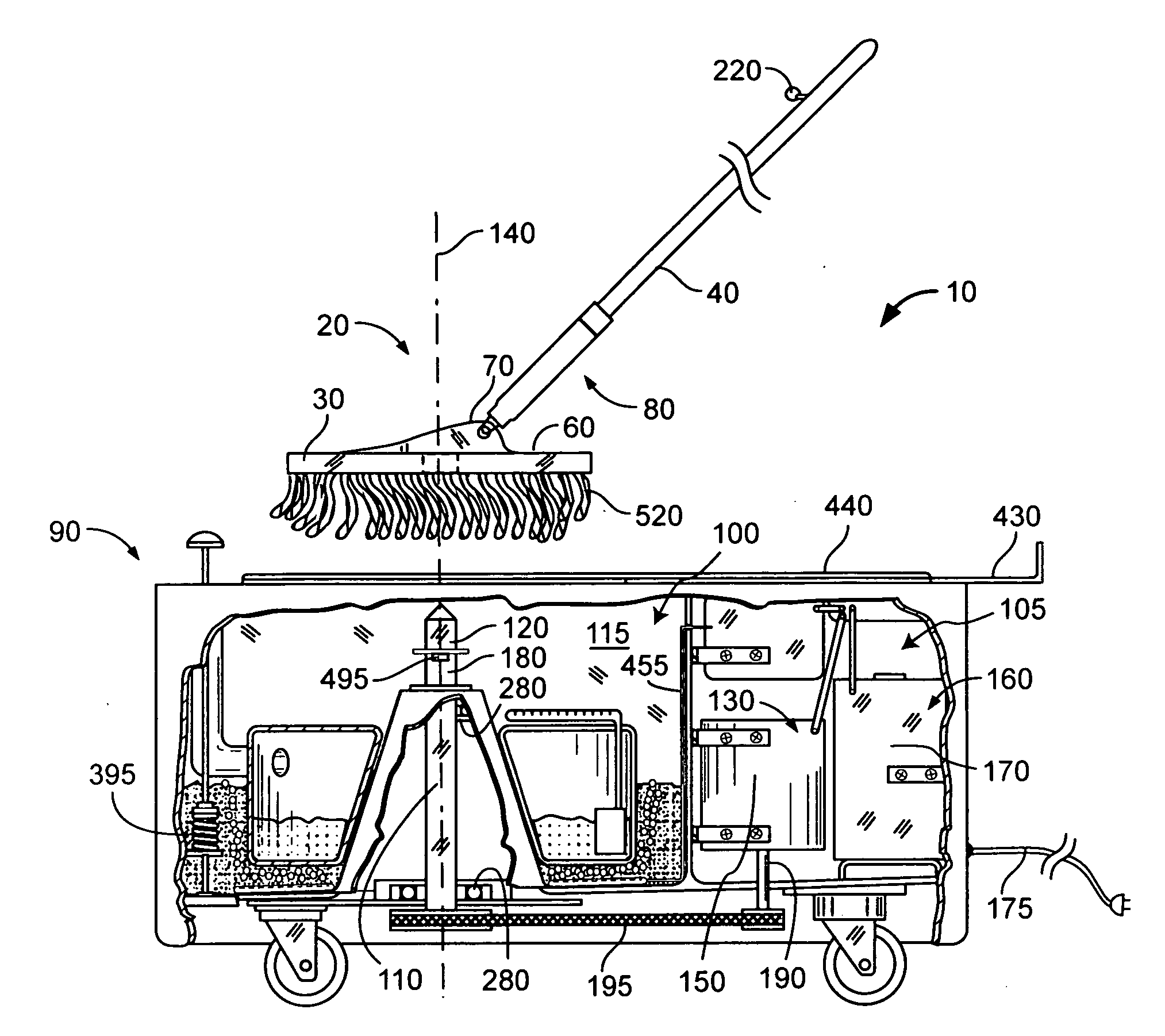
[0023]FIG. 1 illustrates a mopping system 10 of the present invention. In its simplest form, the mopping system 10 comprises a mop assembly 20 and a bucket assembly 90. The mop assembly includes a mop head 30 preferably pivotally attached to an elongated handle 40. The mop head 30 includes a floor-engageable lower surface 50 (FIG. 8) and an opposing upper surface 60. The mop head 30 includes a handle attachment means 70, preferably on the upper surface 60, for attaching the mop head 30 to a lower end 80 of the handle 40 (FIGS. 7-9). The handle attachment means 70 could also be provided on a peripheral edge of the mop head 30 (not shown).

[0024] The mop head 30 is preferably detachable from the elongated handle 40 so that the mop head 30 may be easily spun in the bucket assembly 90 without the need to also spin the handle 40. However, such an arrangement is not necessarily required in an embodiment of the invention that allows for spinning the entire mop assembly 20 by aligning the l...


PUM


Abstract

A mopping system and methods of its use are disclosed. A mop assembly includes a mop head that is adapted to be spun around a generally vertical rotational axis thereof when the mop head is fixed within a mop head spinning means of a bucket assembly. When the mop head is spun at a relatively high rate of rotational speed, water retained in the mop is forcefully dispelled from the mop by centrifugal force. The water leaves the mop and is retained within a spin chamber of the bucket assembly. A drain plunger is included to allow the collected water to be drained from the bucket assembly. An ozone generator may be included for introducing ozone gas into the collected fouled water in the spin chamber. A clean water tank with a pump and spraying means, mounted within the spin chamber just below the mop head when the mop head is engaged with the mop head spinning means, is preferably included to allow introduction of clean water to the moping surface of the mop head. The mop assembly may include a lever means for selectively detaching the mop head from the handle. A control circuit controls the spraying of clean water onto the mop head, the ozone generator, and the activation and speed of the mop head spinning means, such that various wash-dry cycles are available.

Description

FIELD OF THE INVENTION [0001] This invention relates to mops, and more particularly to a mop that has a mop head adapted for spin drying within a motorized bucket assembly. DISCUSSION OF RELATED ART [0002] Conventional mops used in retail and commercial locations such as restaurants, shopping malls, and the like are typically of the type having an elongated handle and a string cloth mop head. A wheeled bucket is usually included that contains either one compartment for a clean water solution, or two compartments for holding the clean water solution and fouled water. A wringer may be included to wring-out the mop into the fouled water compartment. [0003] In use, the mop is wrung-out and submerged into the clean water solution so as to absorb a quantity thereof. Such clean water may also include a cleaning agent such as bleach, or the like. The mop is then applied to the floor where it deposits a layer of the clean water solution and, simultaneously, picks-up dirt, grease and other wa...

Claims


Application Information

Patent Timeline
Patent Type & Authority Applications(United States)
IPC IPC(8): A47L13/58
CPCC02F1/78A47L13/58
Inventor PALMER, ROBERT
Owner SPIN MOP
Why Eureka
Try Eureka