Injection locked high power laser systems

a laser system and laser technology, applied in the direction of laser details, basic electric elements, electrical apparatus, etc., can solve the problems of laser system less efficient, modal instabilities, solid-state laser systems that do not provide diffraction-limited output, etc., and achieve high spectral purity of output and operation stability, the effect of high resistance to optical damag

Inactive Publication Date: 2007-02-22
CORNING INC
View PDF15 Cites 16 Cited by
  • Summary
  • Abstract
  • Description
  • Claims
  • Application Information

AI Technical Summary

Benefits of technology

[0013] The laser systems according to the present invention are capable of providing several advantages: high out put power, for example hundreds of Watts, high spectral purity of output and stability of operation, while also featuring the advantages of compactness, and high resistance to optical damage.

Problems solved by technology

Such solid-state laser systems do not provide a diffraction-limited output, especially when scaled to operate at high powers.
Further, optical birefringence induced at high powers (due to high thermal stresses) results in modal instabilities, and also in depolarization.
In these types of laser systems the solid state (crystal) laser medium has a problem of thermal dissipation, where the crystal absorbs some of the pump light and loses it through heat, thus making the laser system less efficient and making the stable operation at high output powers difficult.
These thermal effects result in instabilities (fluctuations) in both spectral and modal behavior of the laser system output.
However, in such a method of generating deep-ultraviolet light, one has to consider the optical damage to the frequency converter crystal.
This damage arises mainly from the concurrent presence of both the IR and UV light.
This limits the number of hours of operation of the frequency converter crystal before optical damage sets in, resulting in severe loss of conversion efficiency.

Method used


Image

  • Injection locked high power laser systems
  • Injection locked high power laser systems
  • Injection locked high power laser systems

Examples


Embodiment Construction

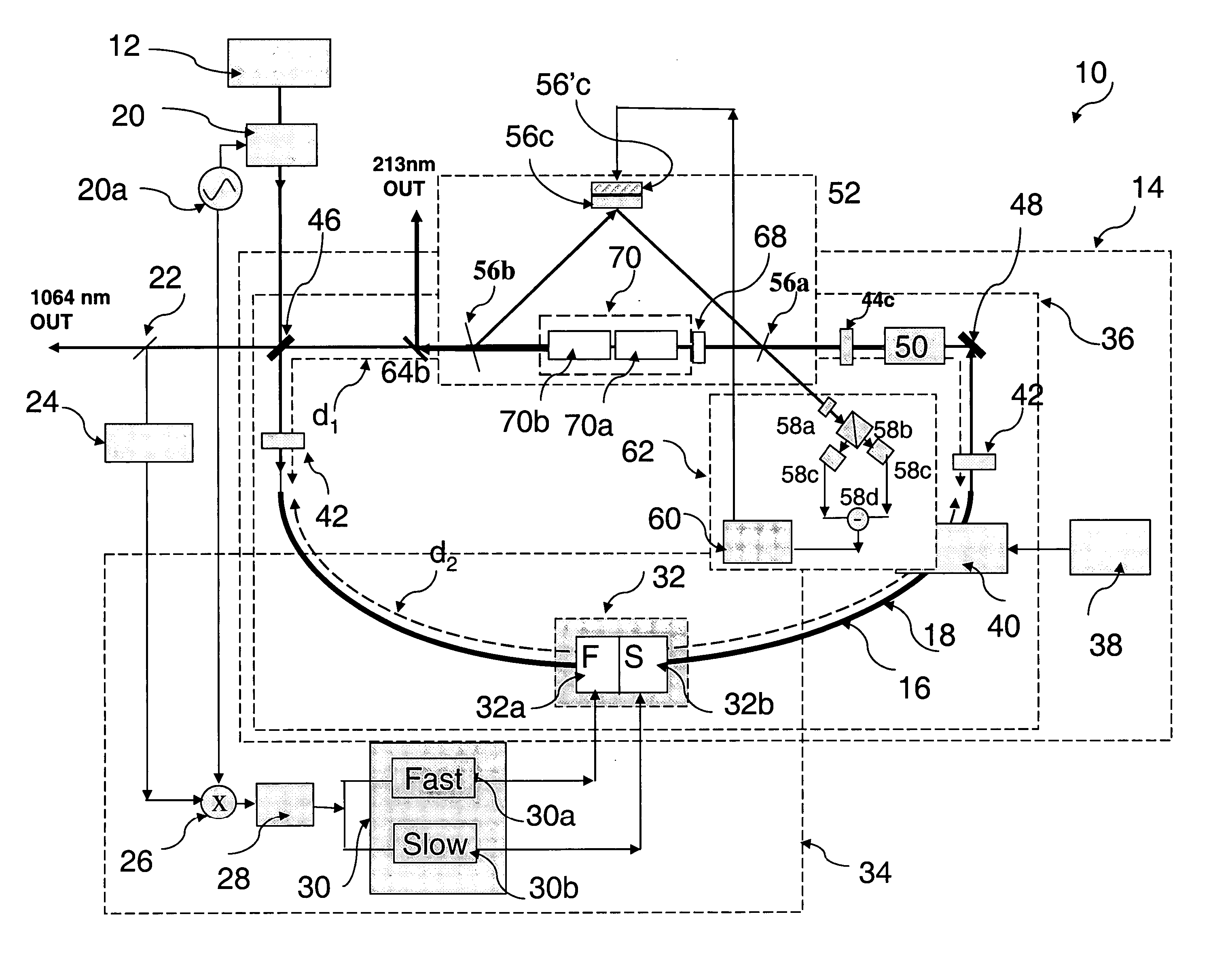
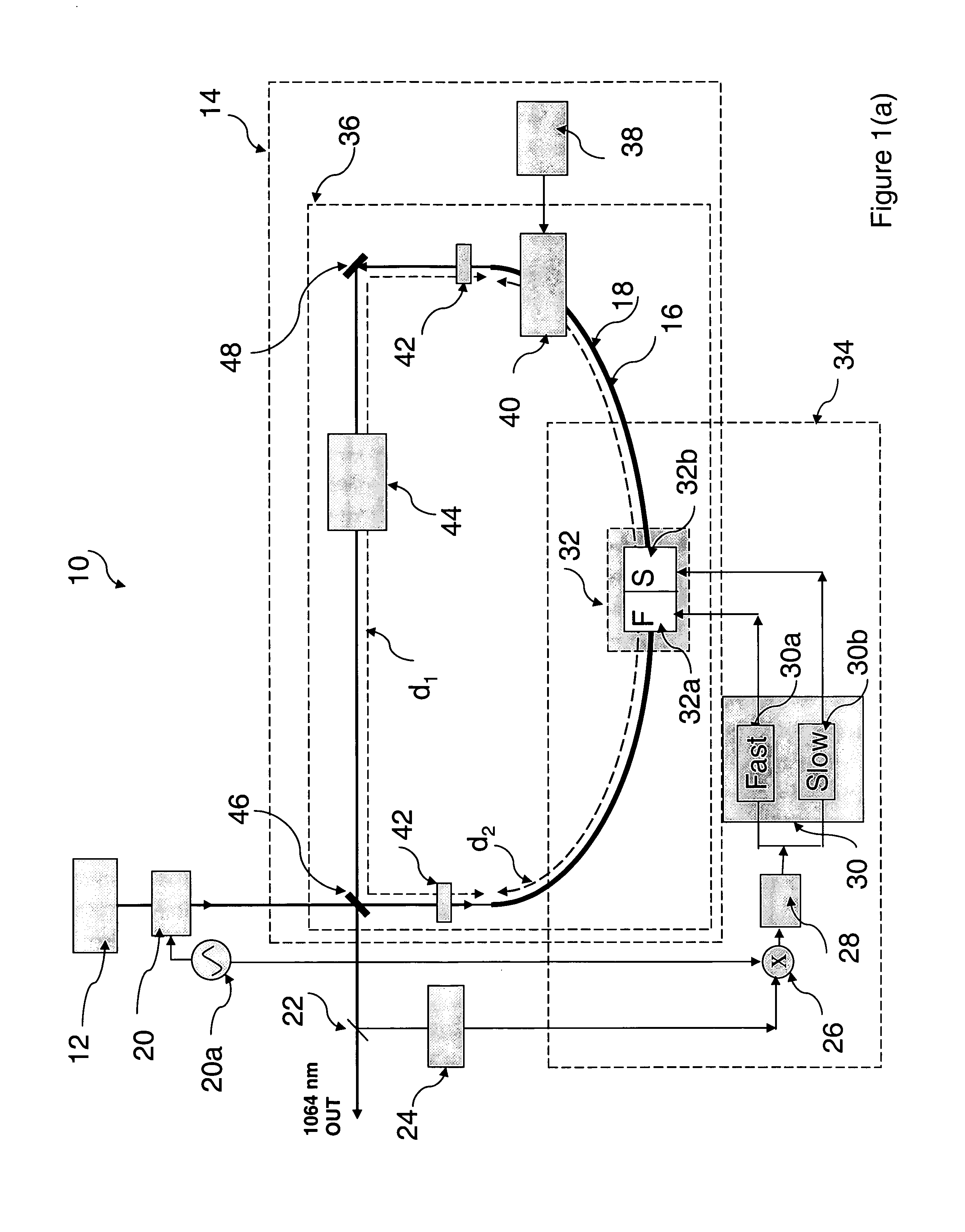
[0023] Referring now to FIG. 1a, illustrated therein is the optical and electronic schematic of an exemplary laser system 10 comprising a low power master laser 12 and a high power slave laser oscillator 14 (also referred to as a primary laser oscillator herein) which includes, as an active medium, a length of rare earth doped fiber 16. The term “oscillator” signifies that the high power slave laser oscillator 14 can independently generate on its own a coherent laser output without the input from the master laser 12, as would be the case when it is not injection-locked to the master laser 12. When active injection locking is not achieved, the spectral linewidth of the high power slave laser oscillator would be broad, for example, as much as 20 nm broad when an Yb doped fiber is utilized. When active injection locking is achieved, the spectral linewidth of the high power slave laser oscillator would become much narrower, for example, 10 pm broad. Thus active injection locking provide...


PUM


Abstract

A high power laser system comprising: a master laser; and a primary slave laser oscillator including a cavity comprising a rare earth doped fiber, said primary slave laser oscillator being actively injection-locked to said master laser, wherein said cavity provides an output exceeding 1 W of optical power.

Description

BACKGROUND OF THE INVENTION [0001] 1. Field of the Invention [0002] The present invention relates generally to high power laser systems which involve the active locking of a high power primary slave laser oscillator to a low power master laser, and particularly to high power rare earth doped double clad fiber hybrid primary slave laser oscillators. [0003] 2. Technical Background [0004] Although high power laser systems comprising a low power master laser injection locked to a primary (slave) laser oscillator are known, such laser systems utilize solid state (i.e., solid laser crystal) gain media. The laser crystal is typically long, about 60 mm, and small in diameter, about 1.6 mm, and is cut at Brewster angle, which results in the crystal having a narrow optical aperture. Thermal lensing in the laser crystal and the narrow aperture of the laser crystal lead to the requirement that the laser cavity length is kept short, typically about 50 cm. The free spectral range of the cavity fc...

Claims


Application Information

Patent Timeline
Patent Type & Authority Applications(United States)
IPC IPC(8): H01S3/30H01S3/098
CPCH01S3/067H01S3/10H01S3/10092H01S3/1086H01S3/109
Inventor SUDARSHANAM, VENKATAPURAM SRIRAMANZENTENO, LUIS ALBERTOKUKSENKOV, DMITRI VLADISLAVOVICHWALTON, DONNELL THADDEUSWANG, JI
Owner CORNING INC
Why Eureka
Try Eureka