
Rotary displacement steam engine

a technology of rotary displacement and steam engine, which is applied in the direction of steam generation using hot heat carriers, machines/engines, indirect heat exchangers, etc., can solve the problems of high rotational speed of the turbine, large scale, complex constitution, etc., and achieve constant torque, efficient operation, and power loss

Inactive Publication Date: 2011-03-29
ISUZU MOTORS LTD
View PDF14 Cites 0 Cited by
  • Summary
  • Abstract
  • Description
  • Claims
  • Application Information

AI Technical Summary

Benefits of technology

The present invention is a steam engine that includes a displacement engine, a steam-generating portion, and a condenser. The engine operates by transferring and refluxing the operation fluid through the displacement engine. The rotor of the engine has multiple operation chambers, and the steam generated by the steam-generating portion is fed into the operation chambers on the side moving upward with the rotation of the rotor. The liquid condensed in the condenser is refluxed into the steam-generating portion on the side moving downward with the rotation of the rotor. The engine is efficient even at low speeds and requires no nozzle, which reduces heat loss and the need for precision bearings. The vacuum pump connected to the condenser can increase the engine output and lower the pressure in the steam-generating portion. The steam-generating portion, displacement engine, and capacitor are arranged in the up-and-down direction, allowing for easy adjustment of the liquid level and efficient operation.

Problems solved by technology

It is not allowed to use the internal combustion engine for converting the heat energy in the natural world or the thermal energy of the internal combustion engine into the mechanical energy.
Therefore, the constitution is complex and is large in scale.
However, when decreasing the diameter of the turbine to miniaturize it, the rotational speed of the turbine becomes very high and a large centrifugal force acts on the turbine and may break it down.
When it is attempted to take out the power in the form of electric energy by a generator, a peripheral control unit and the like being necessary for the high speed generator are complex and expensive.
Therefore, the distance becomes relatively long between the heating portion and the turbine, and the steam is cooled therebetween resulting in a loss of heat.
Further, when the temperature of the heating portion is low and the steam is of a low temperature, the steam is superheated to only a low degree, and water droplets tend to form due to the cooling.
Namely, complex and expensive bearings must be used to support the rotary shaft maintaining sealing performance requiring an increased cost for the maintenance.

Method used


Image

  • Rotary displacement steam engine
  • Rotary displacement steam engine
  • Rotary displacement steam engine

Examples


Embodiment Construction

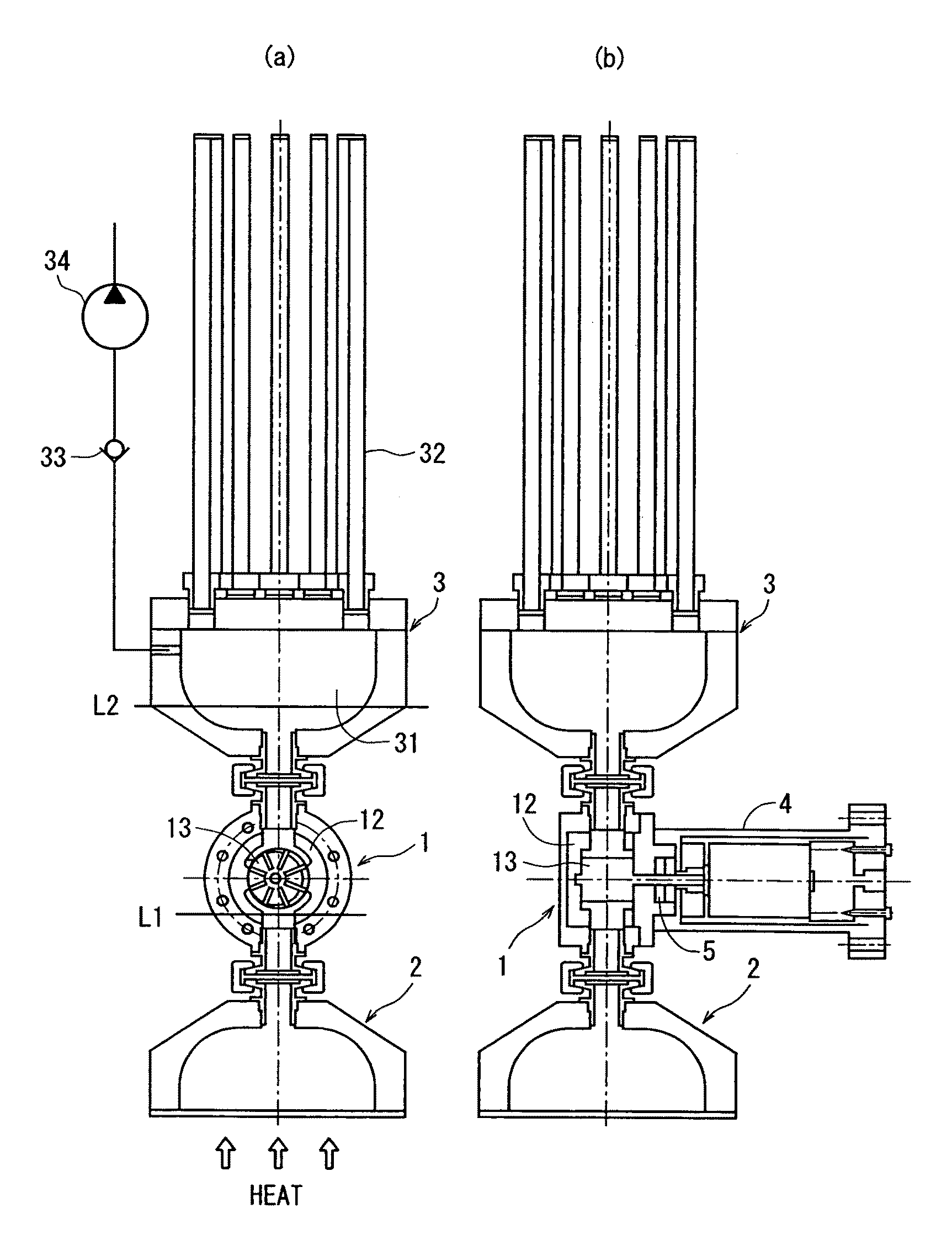
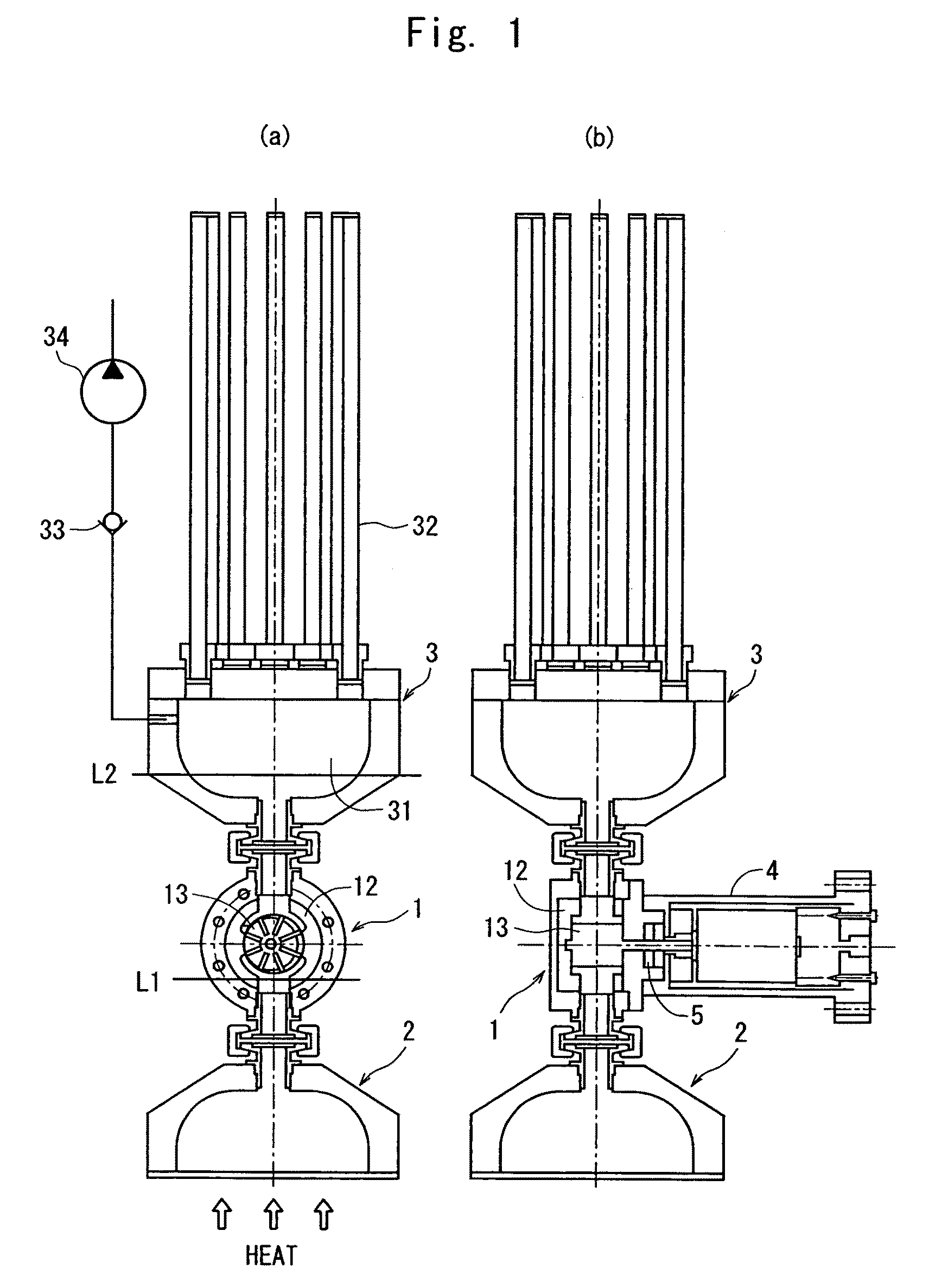
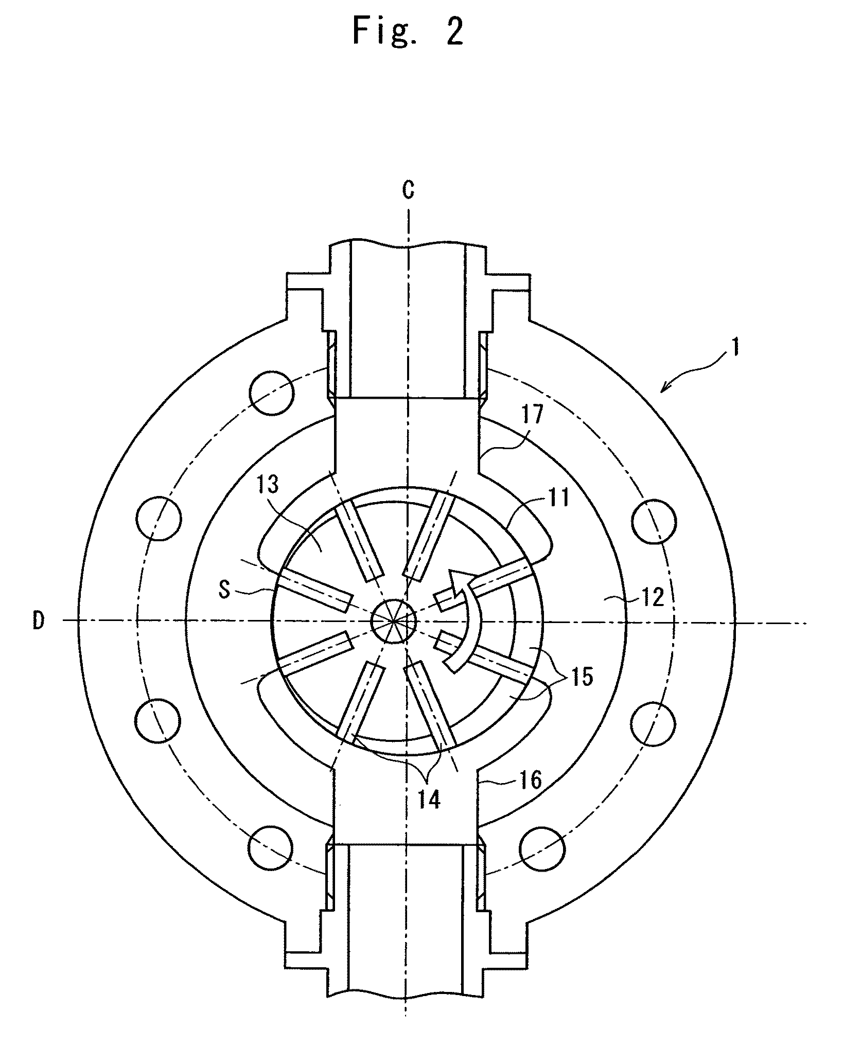
[0026]An embodiment of the invention will now be described in detail with reference to the drawings. FIG. 1 is a sectional view of a steam engine of the present invention, wherein (a) is a central sectional view of a rotor of the displacement engine at right angles with the rotary shaft, and (b) is a sectional view at right angles with (a) and the displacement engine portion includes the rotary shaft of the rotor. FIG. 2 is a sectional view illustrating, on an enlarged scale, the displacement engine.

[0027]The steam engine of the present invention comprises a displacement engine 1 for taking out the power, a steam-generating portion 2 arranged thereunder for generating the steam and a condenser 3 arranged thereover for cooling and condensing the steam. The displacement engine 1, the steam-generating portion 2 and the condenser 3 are connected together through short pipes for coupling and joints, and contain water as an operation fluid therein. When the engine is not in operation, the...


PUM


Abstract

A steam engine of a simple constitution capable of efficiently obtaining mechanical energy not only from a heat source of a high temperature but also from various heat sources in a low-temperature state such as the exhaust heat of an internal combustion engine. The engine comprises a displacement engine 1 having a rotor 13 that rotates, a steam-generating portion 2 arranged thereunder and a condenser 3 arranged thereover. Water heated in the steam-generating portion 2 becomes the steam which is fed into the displacement engine 1, enters into an operation chamber that moves up, rotates the rotor 13 and is, thereafter, fed into the condenser 3 where it is condensed to turn into the condensate. The condensate falls on the rotor 13 on the lower side due to gravity, and is refluxed into the steam-generating portion 2 through the operation chamber that moves downward with rotation of the rotor 13. The steam engine efficiently operates even at low speeds, requires no pump for refluxing the condensate, and is constituted in a compact size.

Description

FIELD OF THE INVENTION[0001]This invention relates to a steam engine for converting thermal energy into mechanical energy such as rotational energy and, more particularly, to a steam engine of a simple constitution for efficiently generating the mechanical energy from a heat source of relatively low temperature.BACKGROUND ART[0002]In recent years, technologies have been developed for utilizing a variety of energy resources from the viewpoint of the environmental measure, saving resources and saving energy. Among them is a technology for taking out the mechanical energy from the thermal energy present in the natural world, such as solar heat. Technologies have also been developed to improve the thermal efficiency of an internal combustion engine by recovering the power which is generated by utilizing the exhaust heat into the exhaust gas or into the cooling water of an internal combustion engine such as diesel engine, and the like.[0003]Heat engines are used for converting the therma...

Claims


Application Information

Patent Timeline
Patent Type & Authority Patents(United States)
IPC IPC(8): F03B17/02F01K11/00
CPCF01C1/18F01C1/3442F01C1/3446F01C11/004F02G5/02F22B1/18F04C2210/242F04C2210/245F04C2210/247F28D2015/0291Y02T10/166Y02T10/12
Inventor YAMAMOTO, YASUSHISAKO, TOMOHISAABE, MAKOTO
Owner ISUZU MOTORS LTD
Learn More