Power steering device

a technology of steering device and power steering shaft, which is applied in the direction of steering initiation, instruments, vessel construction, etc., can solve the problems of lack of actual working fluid pressure, lack of steering assist, and the motor speed threshold value has not yet been reached, so as to increase the burden of car batteries and increase the frequency of operation

Inactive Publication Date: 2007-02-22
HITACHI LTD
View PDF5 Cites 55 Cited by
  • Summary
  • Abstract
  • Description
  • Claims
  • Application Information

AI Technical Summary

Benefits of technology

[0004] However, the hydraulic power cylinder equipped power steering device disclosed in JP2003-137117 is constructed, so that working fluid is pressurized by rotation of the motor-driven reversible pump and the power cylinder is operated by the working fluid pressure produced by the pump. Thus, the power steering device of JP2003-137117 has a motor-speed versus working-fluid-pressure characteristic that the motor speed is fast until the working fluid pressure reaches a predetermined pressure level and the motor speed drops after the predetermined pressure level has been reached. In the case of the aforementioned motor-speed versus working-fluid-pressure characteristic, a time rate of change in motor speed is very high, until the working fluid pressure reaches the predetermined pressure level. Suppose that the actual rate of change in motor speed is less than a desired value while the predetermined pressure level has not yet been reached. Then, a lack of the actual working fluid pressure with respect to the desired fluid pressure value, in other words, a lack of steering assist would result. Under these conditions, suppose that the motor-speed dependent source-voltage boost timing control as disclosed in JP2003-33077 is executed. Then, a response

Problems solved by technology

Then, a lack of the actual working fluid pressure with respect to the desired fluid pressure value, in other words, a lack of steering assist would result.
Then, a response delay in a working fluid pressure rise would result while a motor speed threshold value has not yet been reached.
In such a case, even if the boost operation starts from the boost timing when the motor speed has reached its threshold value, it is impossible to ensure a desired fluid-pressure control responsiveness (i.e., a desired steering assist control responsiveness) and thus it i

Method used


Image

  • Power steering device
  • Power steering device
  • Power steering device

Examples


first embodiment

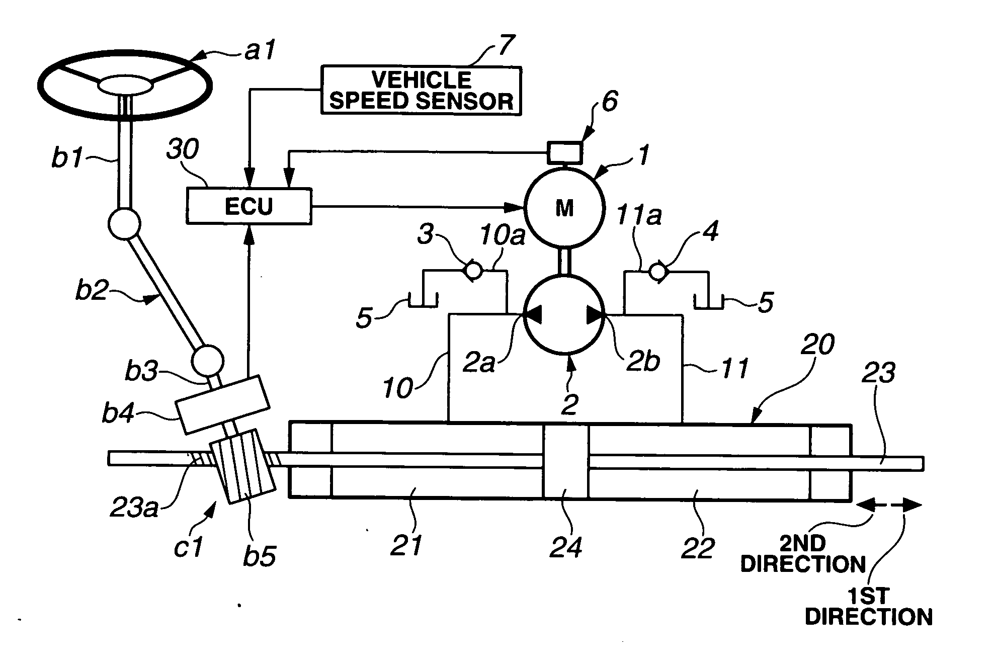
[0034] Referring now to the drawings, particularly to FIG. 1, the power steering device of the first embodiment is exemplified in an automotive vehicle with left and right steered road wheels (not shown). As clearly shown in FIG. 1, a steering wheel a1 is fixedly connected to the top of a steering shaft b1. The upper end of an intermediate shaft b2 is mechanically linked via a universal joint (not numbered) to the lower end of steering shaft b1. The upper end of a pinion shaft b3 is mechanically linked via a universal joint (not numbered) to the lower end of intermediate shaft b2. A torque sensor b4 is installed on or attached to pinion shaft b3, for detecting the magnitude and direction of torque acting between steering wheel a1 and each of the steered road wheels, substantially corresponding to the magnitude and direction of steering torque (steering wheel torque) applied to steering wheel a1 about its axis of rotation by the driver. The torque, detected by torque sensor b4, is he...

second embodiment

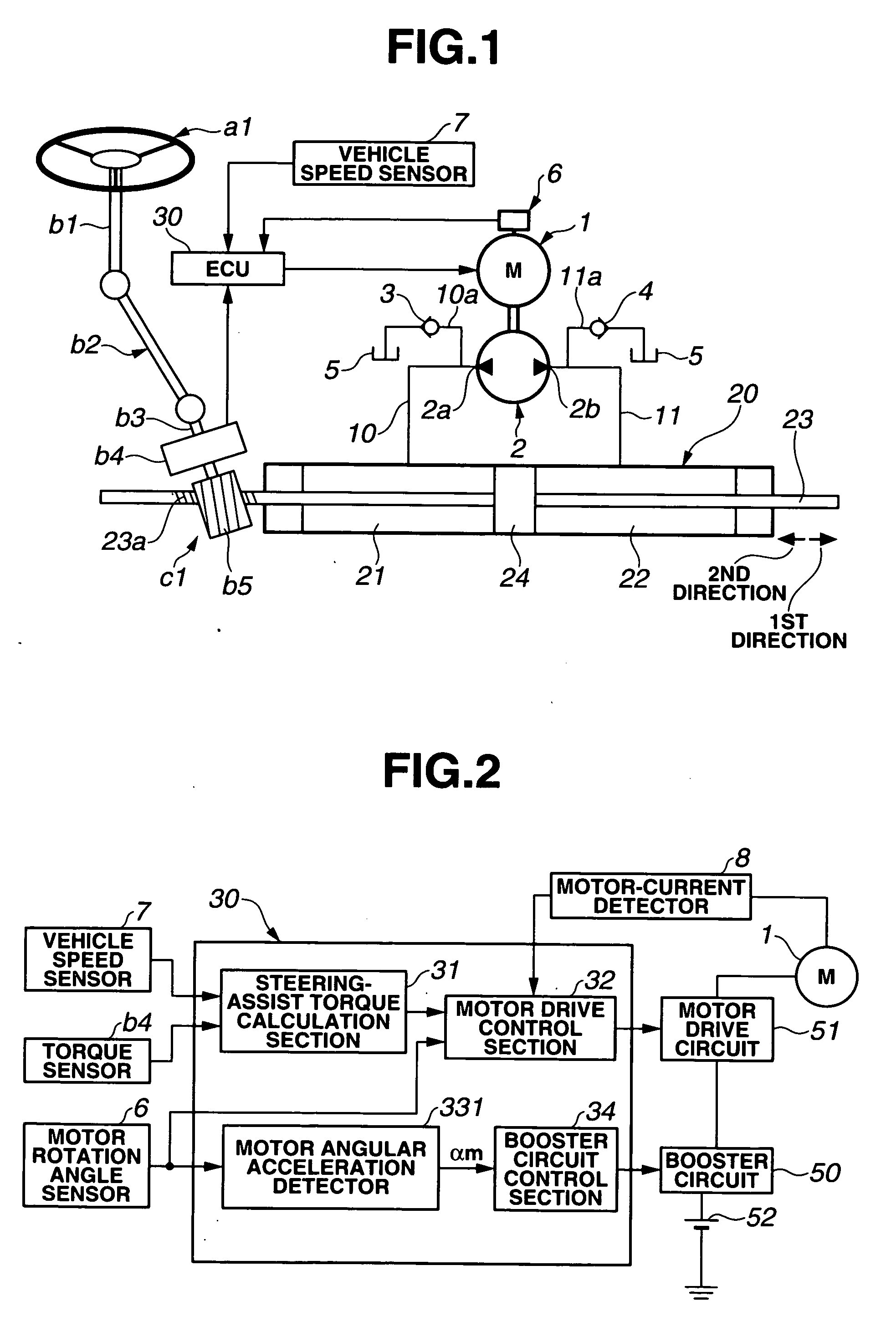
[0066] Referring now to FIG. 7, there is shown the detailed configuration of the control system of the power steering device of the second embodiment. As can be appreciated from comparison of the block diagrams shown in FIGS. 2 and 7, the configuration of the control system of the power steering device of the second embodiment is basically similar to that of the first embodiment. Thus, the same reference signs used to designate elements in the control system of the power steering device of the first embodiment shown in FIG. 2 will be applied to the corresponding reference signs used in the second embodiment shown in FIG. 7, for the purpose of comparison of the two different embodiments. A circuit denoted by reference sign 332 will be hereinafter described in detail with reference to the accompanying drawings, while detailed description of reference signs 1, 6, 7, 8, b4, 31, 32, 50, 51, and 52 will be omitted because the above description thereon seems to be self-explanatory. In the ...

third embodiment

[0076] Referring now to FIGS. 9-10, there is shown the system configuration of the power steering device of the third embodiment. As can be appreciated from comparison of the system diagrams shown in FIGS. 1 and 9 and also appreciated from comparison of the block diagrams of FIGS. 2 and 10, the basic system configuration of the third embodiment is similar to that of the first embodiment. Thus, the same reference signs used to designate elements in the power steering device of the first embodiment shown in FIGS. 1-2 will be applied to the corresponding reference signs used in the third embodiment shown in FIGS. 9-10, for the purpose of comparison of the two different embodiments. A circuit denoted by reference sign 333 and a steering wheel angle sensor (simply, a steering angle sensor) b6 will be hereinafter described in detail with reference to the accompanying drawings, while detailed description of the other reference signs will be omitted because the above description thereon see...


PUM


Abstract

In a power steering device employing a hydraulic power cylinder, a motor-driven pump, and a driving power source for the motor, a power steering control system is configured to electrically connected to at least the motor and the power source for controlling a driving state of the motor and a power source voltage of the power source. The power steering control system includes a motor control circuit that generates a motor driving signal, whose command signal value is determined based on a steering assist force applied through the power cylinder to steered road wheels, a booster circuit that boosts the power source voltage, a motor angular acceleration detection circuit that detects or estimates a motor angular acceleration, and a booster-circuit control circuit that controls, responsively to the motor angular acceleration, switching between operating and non-operating states of the booster circuit.

Description

TECHNICAL FIELD [0001] The present invention relates to a power steering device, and specifically to a hydraulic power cylinder equipped power steering device enabling steering assist force application by operating a hydraulic power cylinder by means of a motor-driven pump. BACKGROUND ART [0002] A power steering device disclosed in Japanese Patent Provisional Publication No. 2003-137117 (hereinafter is referred to as “JP2003-137117”) is generally known as this type of power steering device. The power steering device disclosed in JP2003-137117 is comprised of an output shaft linked to the lower end of a steering shaft, a rack-and-pinion mechanism installed on the lower end of the output shaft for steering of steered road wheels, a hydraulic power cylinder linked to the rack of the rack-and-pinion mechanism, and a motor-driven reversible pump provided for selectively supplying working fluid into the first cylinder chamber arranged as the left-hand half of the power cylinder or into th...

Claims


Application Information

Patent Timeline
IPC IPC(8): B62D6/00
CPCB62D5/046B62D5/0463B62D5/065
Inventor YOKOTA, TADAHARUINOUE, KIYOSHITAKAHASHI, TORU
Owner HITACHI LTD
Why Eureka
Try Eureka