Method for manufacturing gas and liquid storage tanks

a technology for gas and liquid storage tanks, applied in the field of tanks, to achieve the effect of substantial corrosion resistance, high strength, and desirable toughness and ductility

Inactive Publication Date: 2007-03-01
KVA
View PDF34 Cites 10 Cited by
  • Summary
  • Abstract
  • Description
  • Claims
  • Application Information

AI Technical Summary

Benefits of technology

[0021] Subsequent to hardening and assembling the shell components into a storage tank, the shell components may be capable of being used without further heat treatment. However, where improved ductility is desired, preferably the hardened shell components are subjected to a tempering process. Various tempering processes may be conducted as can be selected as those skilled in the art. In a preferred high temperature tempering process, the shell components are heated to between 150° C. and 650° C. In a preferred low temperature tempering process, the shell components are heated to between 130° C. and 180° C. This low temperature tempering process may be conducted simultaneously during an electro-coating process in which the shell components are typically heating to between 130° C. and 180° C. for 20-30 minutes. Subsequent to heating, the shell components are air quenched which results in the automotive fuel tank having a reduced brittleness and corresponding increased toughness and ductility, without a substantial loss in hardness or strength.
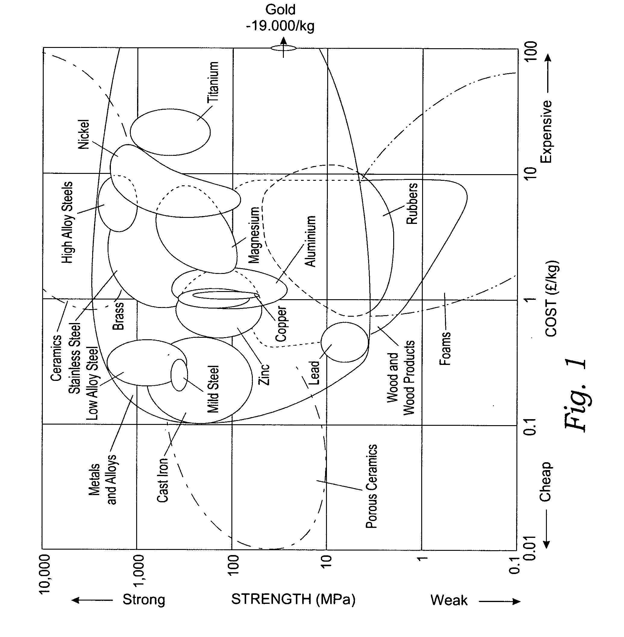
[0024] Advantageously, the manufactured storage tank has high strength, desirable toughness and ductility, and substantial corrosion resistance. Moreover, air-hardenable martensitic stainless steels are relatively inexpensive compared to many other steel alloys or composite materials which results in automotive fuel tanks having improved functional properties at a reduced cost.
[0025] It is thus an object of the present invention to provide a high strength low cost process for manufacturing, storage tanks and particularly automotive fuel tanks.

Problems solved by technology

However, the secondary heat source provides heat at a sufficiently high temperature and maintains heat for sufficiently long so as to reduce the hardness of the weld.

Method used


Image

  • Method for manufacturing gas and liquid storage tanks
  • Method for manufacturing gas and liquid storage tanks
  • Method for manufacturing gas and liquid storage tanks

Examples


Embodiment Construction

[0036] While the present invention is susceptible of embodiment in its various forms, there is shown in the drawings and will be hereinafter be described the presently preferred embodiments of the invention with the understanding that the present disclosure is to be considered as exemplifications of the invention and it is not intended to limit the invention to the specific embodiments illustrated.

[0037] As illustrated in FIGS. 4-8, the present invention is directed to a method of manufacturing tanks for storing gases and liquids. Because the method of manufacturing tanks is particularly useful for producing automotive fuel tanks, the invention will hereinafter be described for fabricating an automotive fuel tank. However, the present invention is not intended to be unduly limited to producing automotive fuel tanks, and indeed, the invention may be utilized to produce a wide variety of gas or liquid storage tanks including but not limited to scuba tanks, propane tanks, vehicle and ...


PUM

PropertyMeasurementUnit
temperatureaaaaaaaaaa
thicknessaaaaaaaaaa

Abstract

A method for making gas and liquid storage tanks such as automotive fuel tanks includes providing two or more blanks of air hardenable martensitic stainless steel in the annealed condition. The steel blanks have a thickness in the range of 0.5-5.0 mm., and are formed utilizing stamping, forging, pressing, or roller forming techniques or the like into the form of a tank shell components. The shell components are hardened and assembled into a storage tank. The shell components are hardened by application of heat, preferably to between 950° C. and 1100° C. for standard air hardenable martensitic stainless steels. Thereafter, the automotive fuel tank is preferably cooled at a rate greater than 25° C. per minute to achieve a Rockwell C hardness of at least 39. The automotive fuel tank may undergo additional heat treating processes including high temperature or low temperature tempering processes which may incorporate electro-coating.

Description

RELATED APPLICATIONS [0001] This application is a continuation-in-part application of pending U.S. application Ser. No. 11 / 519,331 filed on Sep. 11, 2006, which is in turn a continuation-in-part application of pending U.S. application Ser. No. 10 / 519,910 filed on Dec. 30, 2004, which is in turn, a National Phase application of International Application Serial No. PCT / US02 / 20888 filed on Jul. 1, 2002, which in turn, claims priority to U.S. Provisional Application No. 60 / 301,970 filed on Jun. 29, 2001.BACKGROUND OF THE INVENTION [0002] The present invention relates to tanks for storing gases and liquids. More particularly, the present invention relates to a method of manufacturing fuel tanks for automobiles and trucks. [0003] It is preferred that automotive fuel tanks be lightweight, and of a sufficient strength and durability to meet automotive safety requirements. In addition, automotive fuel tanks must be able to contend with harsh environmental conditions, and thus must be corrosi...

Claims


Application Information

Patent Timeline
Patent Type & Authority Applications(United States)
IPC IPC(8): A47J36/02
CPCC21D6/002Y10T29/49622C22C38/40C21D9/0068
Inventor MCCRINK, EDWARD J.CODD, DANNY
Owner KVA
Why Eureka
Try Eureka