Liquid crystal display and method for manufacturing the same

Active Publication Date: 2007-03-01
AU OPTRONICS CORP
View PDF18 Cites 16 Cited by
  • Summary
  • Abstract
  • Description
  • Claims
  • Application Information

AI Technical Summary

Benefits of technology

[0022] Therefore, the disclosed manufacturing method of the transflective LCD has the following advantages: (1) it uses a single cell gap design to avoid the complexity in the process for the dual cell gap design; (2) it uses a single cell gap design and a single control circuit to control the transmi

Problems solved by technology

However, it is more difficult for the reflective display to achieve high contrast and high color quality (particularly full colors) at high resolutions.
Moreover, when the environmental light source provides insufficient light, the contrast and brightness of the reflective display are greatly reduced.
However, when the cell gaps of the transmissive region and the reflective region are the same, the transmittance vs. voltage curve of the

Method used


Image

  • Liquid crystal display and method for manufacturing the same
  • Liquid crystal display and method for manufacturing the same

Examples


Embodiment Construction

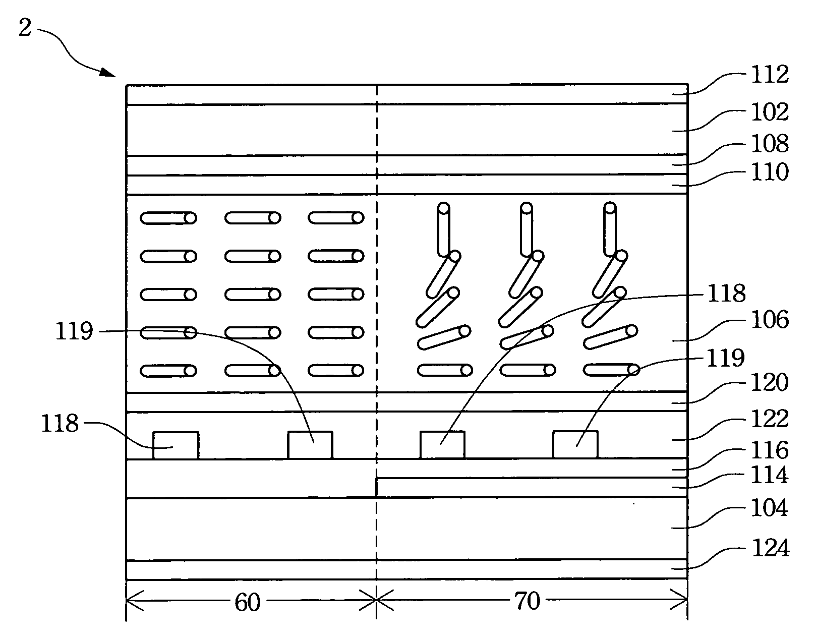
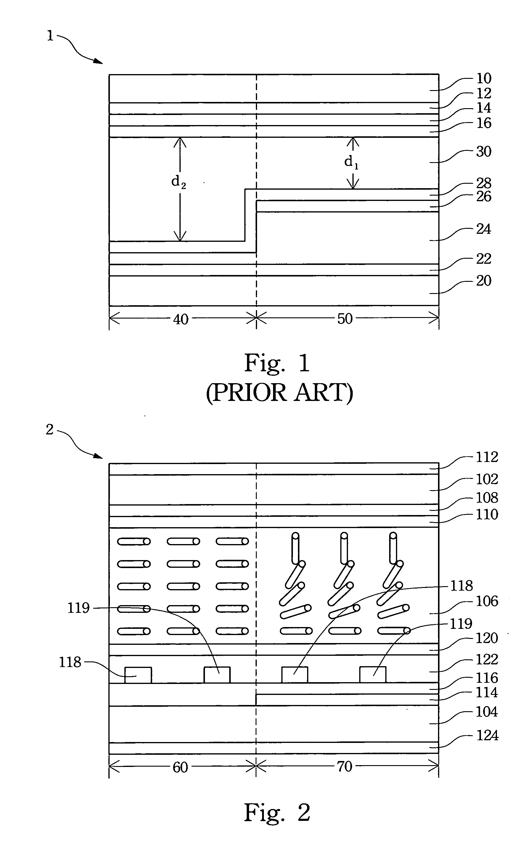
[0026] The present invention will be apparent from the following detailed description, which proceeds with reference to the accompanying drawings, wherein the same references relate to the same elements. With reference to FIG. 2, a transflective display panel 2 has a transmissive region 60 and a reflective region 70. The transflective display panel 2 further contains a pair of parallel upper substrate 102 and lower substrate 104, and a liquid crystal layer 106 filled in the gap between the upper substrate 102 and the lower substrate 104. The inner surface of the upper substrate 102, i.e., the one facing the liquid crystal layer 106, is coated with a color filter 108 and a first alignment film 110. The color filter 108 includes an array of red, blue, and green color films and a black matrix film. The outer surface of the upper substrate 102 is coated with a first polarization film 112. The upper substrate 102 and the lower substrate 104 are transparent substrates, such as glass subst...


PUM


Abstract

A liquid crystal display with transmissive region and reflective region is provided. The display comprises an upper substrate and a lower substrate, which is settled in parallel with the upper substrate. A reflective layer is located on the reflective region of the lower substrate and an insulation layer covers the reflective layer and the lower substrate. Positive and negative driving electrodes are chiastically settled on the insulation layer. A first alignment film is positioned on the inner surface of the upper substrate, and the alignments of the first alignment film on the transmissive region and reflective region are different. A second alignment film covers the insulation layer, the positive and negative electrodes. A liquid crystal layer is located between the first alignment film and the second alignment film.

Description

RELATED APPLICATIONS [0001] The present application is based on, and claims priority from, Taiwan Application Serial Number 94128814, filed Aug. 23, 2005, the disclosure of which is hereby incorporated by reference herein in its entirety. BACKGROUND OF THE INVENTION [0002] 1. Field of Invention [0003] The invention relates to the production method of a liquid crystal display (LCD) and, in particular, to the manufacturing method of a transflective LCD. [0004] 2. Related Art [0005] Opto-electronic technologies have recently made tremendous progress, pushing the rapid development in liquid crystal displays (LCD) in the digital era. The LCD has the advantages of high picture quality, small volume, light weight, low driving voltage and power consumption. Therefore, they are widely used in personal digital assistants (PDA), mobile phones, camcorders, notebook computers, desktop displays, vehicle displays, and projection televisions. They have replaced the conventional cathode ray tubes (C...

Claims


Application Information

Patent Timeline
IPC IPC(8): G02F1/1335
CPCG02F1/133753G02F1/133788G02F2001/133773G02F2001/133757G02F1/134363G02F1/133773G02F1/133757
Inventor LIN, TZU-YUANCHIANG, CHUN-HUNGHSIEH, FU-CHENGWU, PO-CHANGHUANG, REN-HUNGWU, JIN-JEICHANG, CHIH-MINGCHEN, PO-LUN
Owner AU OPTRONICS CORP
Why Eureka
Try Eureka