
Ultrasonic color imaging characterizing ultra-fine structures and continuously distributed physical conditions

a color imaging and ultra-fine structure technology, applied in the direction of distance measurement, instruments, digital computer details, etc., can solve the problems of reducing the accuracy of ultrasonic color imaging, ignoring valuable information left unutilized in conventional ultrasonic imaging for decades, and reducing the false detection rate. , the effect of reducing the false detection ra

Inactive Publication Date: 2007-03-01
CLEAR SOUNDS TECH SHANGHAI CO LTD
View PDF4 Cites 9 Cited by
  • Summary
  • Abstract
  • Description
  • Claims
  • Application Information

AI Technical Summary

Benefits of technology

[0026] a) Presentation wise, it possesses the efficiency and spatial perception of images, the straightforwardness and exactness of numerical readings, and the informational richness and insightfulness of signal traces.
[0027] b) Hardware cost wise, it is in the range of ultrasonic flaw detectors, not much ultrasonic imaging systems.
[0028] c) Applicability wise, it works on any spots where traditional NDT flaw detection or erosion inspection can be performed.
[0030] e) Operation wise, the intuitively understandable visual presentation, and the significantly reduced rate of false detection and failed detection, making ultrasonic NDT significantly easier and preferable.

Problems solved by technology

Unfortunately, traditional ultrasonic inspections only deal with discontinuities, not continuously distributed conditions.
Unfortunately, such invaluable information has been left unused in conventional ultrasonic imaging for decades.
However, this improvement is still limited in the way that image points on the same sound path (same scan line) and confined by the same pair of interfaces are represented either identically, or in monotonically changing manner.
No effective means of charactering or imaging such acoustic conditions are commercially available.
Some very thin sheet targets, such as the blades of an aircraft engine or power generator operating at extremely high speed, while being most vulnerable to interior defects, are the hardest to inspect by conventional ultrasonic inspections, due to the simple fact that tiny echoes generated by defects are buried in much larger echoes contributed by the front and back exterior walls.
Continuous defects that distort rather than reflect sound signals, are by far more harmful to thin targets than to thicker targets, but are even harder to detect.
The information that a single glimpse sends to the brain, if to play out in audio frequencies, can take years of listening.
Not surprisingly, this most desired presentation, known as four dimensional imaging, is produced by very expensive ultrasonic imaging systems.
On the other end, the numerical thickness readings presented by ultrasonic thickness gauges, although efficient in conveying measurement results, provide no spatial perception.
Many thickness gauges use a sound beep to alert the occurrence of pre-defined thickness reading, indicating that numerical readings alone can not fulfill the task satisfactorily.
However, users are unable, or to larger extent, unwilling to deal with signal traces because of their poor visual image.
Ultrasonic erosion inspection and flaw detection are rarely performed by imaging systems despite of all the merits of image, not only because imaging systems are prohibitively expensive for typical NDT operation budgets, but also due to the operability limitations of imaging systems.
Transducer arrays used in medical imaging can manage an adequate acoustical contact with soft human bodies, but not on rigid, curved surfaces and small facets, and are not practical when the test spots have narrow accesses, high temperature, or other severe conditions.
Mechanical scan require good acoustic coupling between the transducer and target without changing target's positioning, which is achieved either by running a stream of coupling agent between the transducer and the target throughout the inspection, or by immersing the scan mechanism in a tank filled with coupling agent (water or oil)—not feasible for most NDT situations.

Method used


Image

  • Ultrasonic color imaging characterizing ultra-fine structures and continuously distributed physical conditions
  • Ultrasonic color imaging characterizing ultra-fine structures and continuously distributed physical conditions
  • Ultrasonic color imaging characterizing ultra-fine structures and continuously distributed physical conditions

Examples


Embodiment Construction

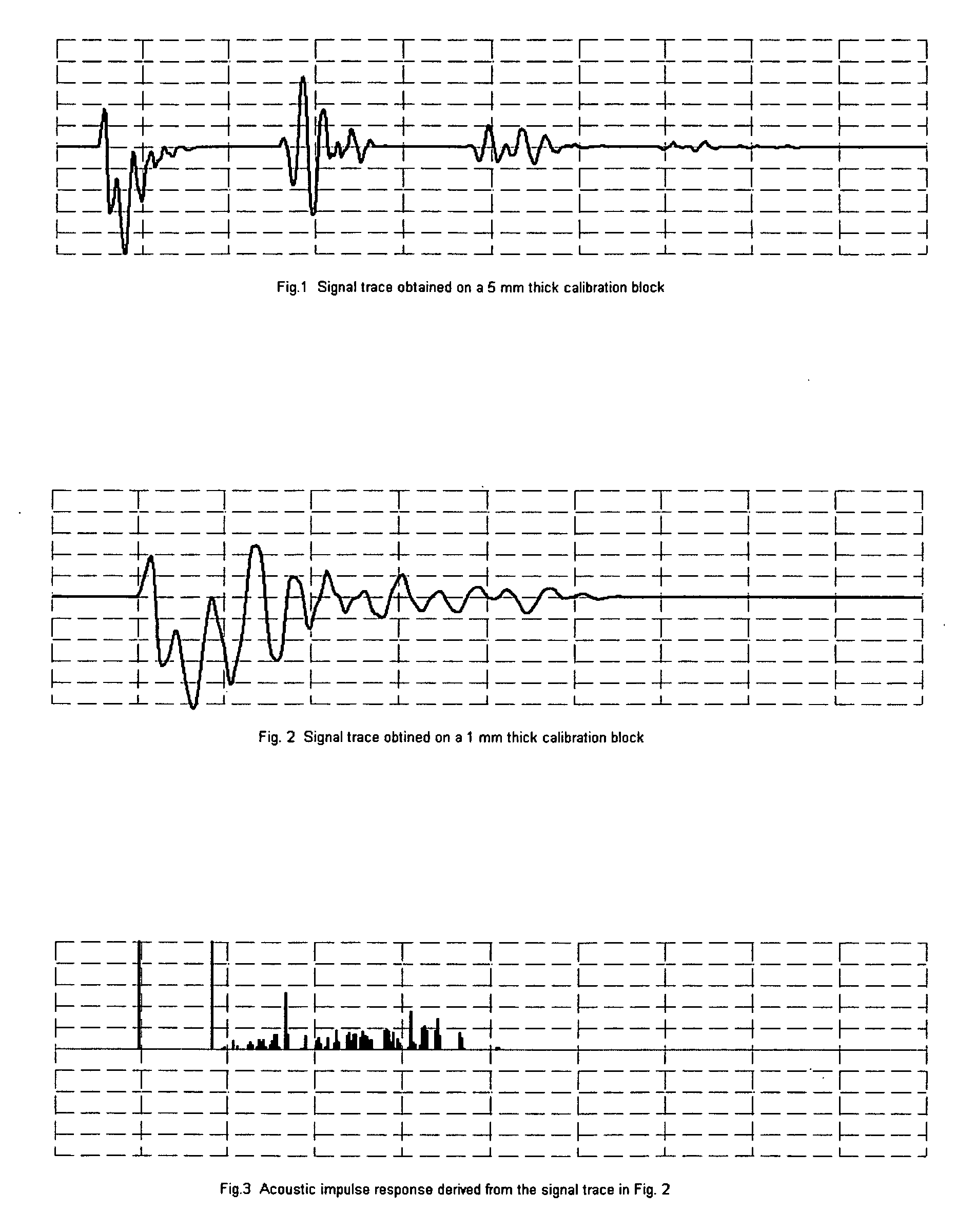
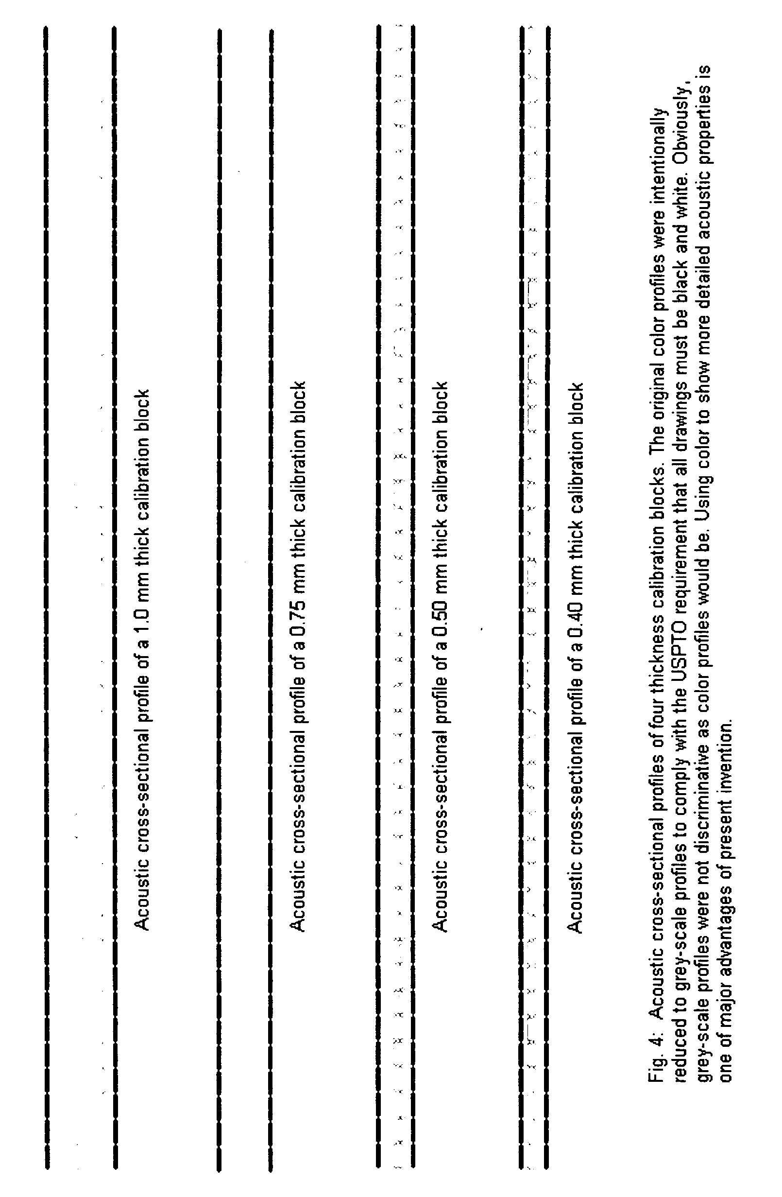
[0031] This invention discloses methods and apparatus for ultrasonic color imaging that characterizes ultra-fine structures and distributional physical conditions within the target under inspection. The disclosed method complementarily incorporates information arising from a plurality of repeated sound trips forced by repeated reflections of exterior and interior interfaces of target, and visualizes the information into an image segment representing the main path that ultrasonic signals have traveled within the target. An image that is substantially more discriminative, descriptive, and position-sensitive to both acoustic interfaces and distributional acoustic characteristics of the target, is achieved as the result.

[0032] The invention is especially useful for thin sheet targets most vulnerable to both non-continuous and continuous interior defects. The continuous interior conditions and effects of ultra-thin layered structures are effectively expressed in color image details.

[00...


PUM


Abstract

This invention discloses methods and apparatus for ultrasonic color imaging that characterizes ultra-fine structures and distributional physical conditions within the target under inspection. The disclosed complementarily incorporates information arising from a plurality of repeated sound trips forced by repeated reflections of exterior and interior interfaces of target, and expresses the information into an image segment representing the main path that ultrasonic signals traveled within the target. The image produced is substantially more discriminative, descriptive, and position-sensitive to both acoustic interfaces and distributional acoustic characteristics of the target. The invention is especially useful for thin sheet targets most vulnerable to both non-continuous and continuous interior defects. The continuous interior conditions and effects of ultra-thin layered structures, that traditional ultrasonic inspection has been unable to express, are effectively expressed by linking their effects of deforming the waveform of passing ultrasonic signals to color image details.

Description

CROSS-REFERENCE OF RELATED APPLICATIONS [0001] This application claims the benefit of U.S. provisional application “Ultrasonic Sectional Profiling Using Multi-Reflection Information in Multi-Parameter Color Image Presentation”, Ser. No. 60 / 707,940, filed on Aug. 15, 2005 by the present inventor.FIELD OF INVENTION [0002] The present invention relates to the field of non-destructive ultrasonic medical and industrial inspections. In particular it relates to ultrasonic color imaging for medical and material inspection and characterization. VOCABULARY AND DEFINITIONS [0003] Trace, signal trace, amplitude trace, amplitude response: All these phrases are used to refer to same thing—varying signal amplitude as a function of time. It is also known as “A-Scan” (meaning Amplitude-Scan) in ultrasonic NDT community. Usually can be directly and reliably obtained, a signal trace provides the most first-hand information resource for almost all ultrasonic inspections, including thickness gauging, fl...

Claims


Application Information

Patent Timeline
IPC IPC(8): G06K9/36
CPCG01N29/043G01N29/06G01S7/52071G01N2291/02854G01N2291/0237
Inventor WEN, JING JIANG
Owner CLEAR SOUNDS TECH SHANGHAI CO LTD
Learn More